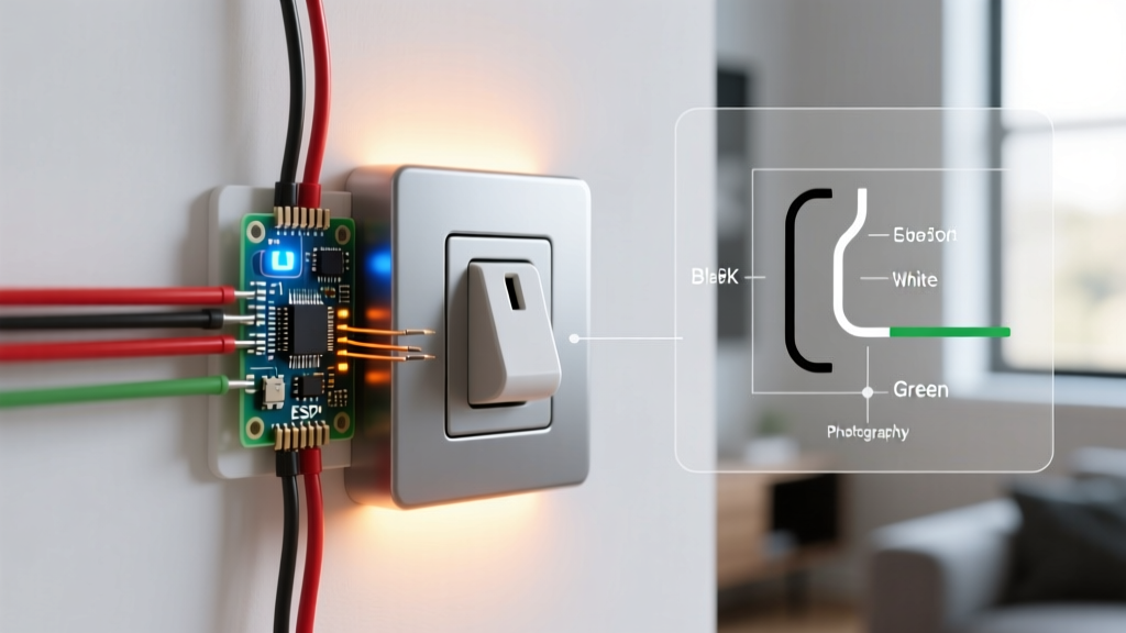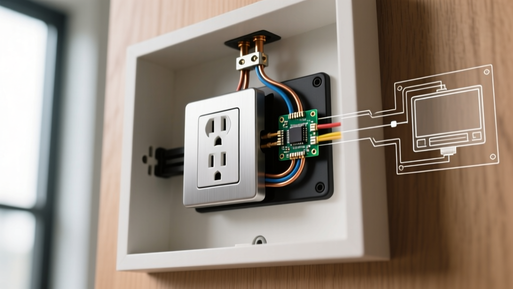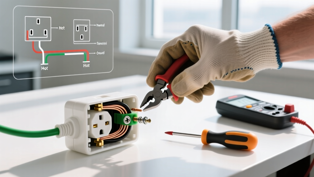

Introduction to US Plug Wiring Standards
When dealing with US electrical plug wiring, understanding the National Electrical Manufacturers Association (NEMA) configurations is only the first step. Whether you are wiring a standard NEMA 5-15P (15A, 125V) replacement plug for a power tool or terminating a heavy-duty NEMA 14-50P (50A, 125/250V) for an EV charger, the integrity of your termination dictates the safety of the entire circuit. According to the National Fire Protection Association (NFPA), faulty cord terminations and loose plug connections are leading causes of residential and industrial electrical fires.
This comprehensive inspection and testing guide moves beyond basic receptacle testers. We will cover advanced multimeter diagnostics, visual strain relief inspections, and the precise torque specifications required by modern electrical codes to ensure your plug wiring is safe, compliant, and built to last.
Essential Testing Tools for 2026
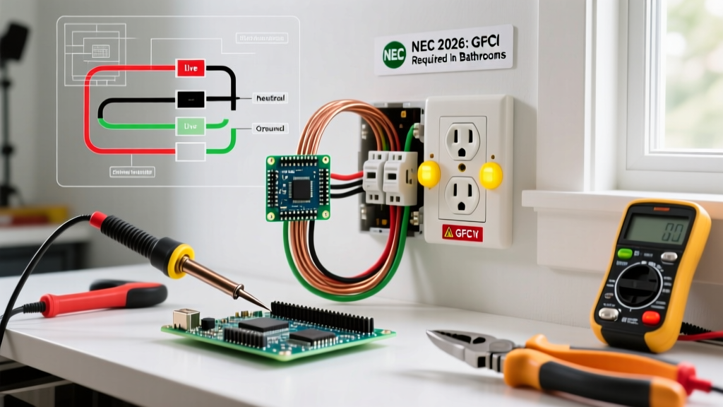
To properly inspect US electrical plug wiring, you need tools that provide quantitative data, not just pass/fail LED indicators. Here is the professional toolkit required for thorough diagnostics:
- True-RMS Digital Multimeter (DMM): A Fluke 117 or Klein Tools MM700 (approx. $200–$250) is essential for accurate AC voltage and resistance readings, especially on circuits with non-linear loads.
- Advanced Receptacle Tester: The Amprobe INSP-3 or Klein Tools RT250 ($40–$180) can detect bootleg grounds and measure exact ground-to-neutral voltage thresholds.
- Insulated Screwdrivers & Nut Drivers: Wiha or Klein insulated sets rated for 1000V to prevent accidental shorts during live-terminal inspections.
- Torque Screwdriver: A calibrated torque driver (e.g., Wiha TorqueVario-S) to verify terminal screw tension to manufacturer specifications.
Visual Inspection: Strain Relief & Terminal Integrity
Before applying power, a rigorous visual and physical inspection of the plug cap is mandatory. The most common failure point in US electrical plug wiring is improper strain relief.
Identifying Common Failure Modes
- Jacket vs. Conductor Clamping: The cord grip (strain relief clamp) inside the plug cap MUST bite down on the outer insulating jacket of the cable, not the individual colored conductors. If the clamp pinches the copper strands or the inner insulation, the wire will eventually sever under mechanical stress.
- Exposed Copper Strands: When stripping the conductors, no bare copper should be visible outside the terminal connection. Exposed strands outside the terminal block create a shock hazard and increase the risk of phase-to-phase short circuits.
- Undersized Cord Caps: Never force a 12 AWG (20A) cable into a plug cap designed strictly for 16 AWG or 14 AWG wire. The internal geometry will prevent the strain relief from engaging properly.
Safety Warning: Always verify the circuit is de-energized using a non-contact voltage tester (NCVT) and a multimeter before opening a plug cap or touching terminal screws. The Occupational Safety and Health Administration (OSHA) mandates strict lockout/tagout (LOTO) procedures for industrial cord inspections.
Step-by-Step Multimeter Testing Protocol
Once the visual inspection is complete and the plug is wired, you must verify the electrical continuity and polarity before connecting it to a load.
Phase 1: Dead Circuit Continuity Testing
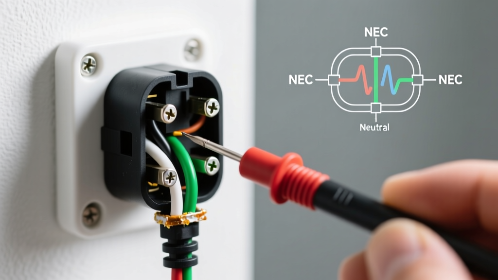
With the plug disconnected from any power source, set your DMM to the continuity or low-ohms resistance setting.
- Hot Verification: Place one probe on the brass (shorter) prong of the plug and the other on the exposed copper end of the black (hot) wire. Expected reading: < 1.0 Ω.
- Neutral Verification: Test the silver (longer) prong to the white (neutral) wire. Expected reading: < 1.0 Ω.
- Ground Verification: Test the round U-shaped pin to the green/bare (ground) wire. Expected reading: < 1.0 Ω.
- Short Circuit Check: Test Hot to Neutral, Hot to Ground, and Neutral to Ground. All readings must show 'OL' (Open Line / Infinite Resistance). Any continuity here indicates a fatal wiring short.
Phase 2: Live Voltage & Polarity Verification
Plug the cord into a known-good, properly wired receptacle. Set your DMM to AC Voltage (V~).
| Test Points | Expected Reading (120V Circuit) | Diagnostic Meaning |
|---|---|---|
| Hot to Neutral | 115V – 125V | Confirms correct polarity and adequate supply voltage. |
| Hot to Ground | 115V – 125V | Confirms the grounding path is intact back to the panel. |
| Neutral to Ground | < 2.0V | Confirms no shared neutrals or severe voltage drop on the neutral leg. |
Advanced Diagnostics: Bootleg Grounds & High-Resistance Faults
A 'bootleg ground' occurs when a previous installer wired a jumper between the neutral terminal and the ground terminal inside a receptacle or plug to trick standard 3-light testers into showing a 'Correct' reading. This is incredibly dangerous; if the neutral wire breaks upstream, the metal chassis of the connected appliance becomes energized at 120V.
How to test for a bootleg ground: Use an advanced tester like the Amprobe INSP-3, which sends a high-frequency signal to differentiate between a true equipment grounding conductor and a neutral-to-ground jumper. Alternatively, measure the Neutral-to-Ground voltage under a heavy load (e.g., running a 1500W space heater). If the N-G voltage rises significantly (above 3V-5V), the ground path is likely sharing the neutral return current, indicating a bootleg or a severe neutral bond fault.
NEC Compliance & Torque Specifications
The National Electrical Code (NEC) has increasingly emphasized the importance of proper termination torque. Loose terminal screws cause high-resistance connections, leading to arcing, melting plug caps, and fires. According to NEC Article 110.14(D) and guidelines supported by Electrical Safety Foundation International (ESFI), terminations must be tightened to the manufacturer's specified torque.
For standard 15A and 20A NEMA 5-15P and 5-20P replacement plugs, the typical terminal screw torque specification ranges between 12 in-lbs and 14 in-lbs. Always check the stamp on the plug cap or the manufacturer's datasheet. Using a calibrated torque screwdriver ensures the copper strands are compressed sufficiently to prevent thermal expansion and contraction from loosening the connection over time.
Frequently Asked Questions
Why is my Neutral-to-Ground voltage reading above 2V?
A Neutral-to-Ground (N-G) voltage reading above 2V under load typically indicates voltage drop on the neutral conductor. This happens when the circuit is heavily loaded, the wire run is exceptionally long (exceeding 100 feet on 14 AWG), or the neutral is undersized. In multi-wire branch circuits (MWBCs), it can also indicate a loose neutral bus bar connection in the main panel.
Can I use a standard 15A receptacle tester for a 20A NEMA 5-20P plug?
No. A NEMA 5-20P plug features a T-shaped neutral blade designed for 20A circuits. Standard 15A testers will not physically fit into a 5-20P plug cap. You must use an adapter specifically rated for 20A testing or use a multimeter to probe the exposed prongs carefully (using proper PPE) to verify polarity and ground continuity.
What is the correct wire strip length for plug terminals?
Most standard US replacement plugs feature a strip gauge molded into the plastic housing. Generally, stripping exactly 1/2 inch to 5/8 inch of insulation is ideal. The goal is for the copper wire to wrap fully around the terminal screw (if using loop terminations) or seat completely inside the pressure plate without any bare copper being exposed outside the terminal block.