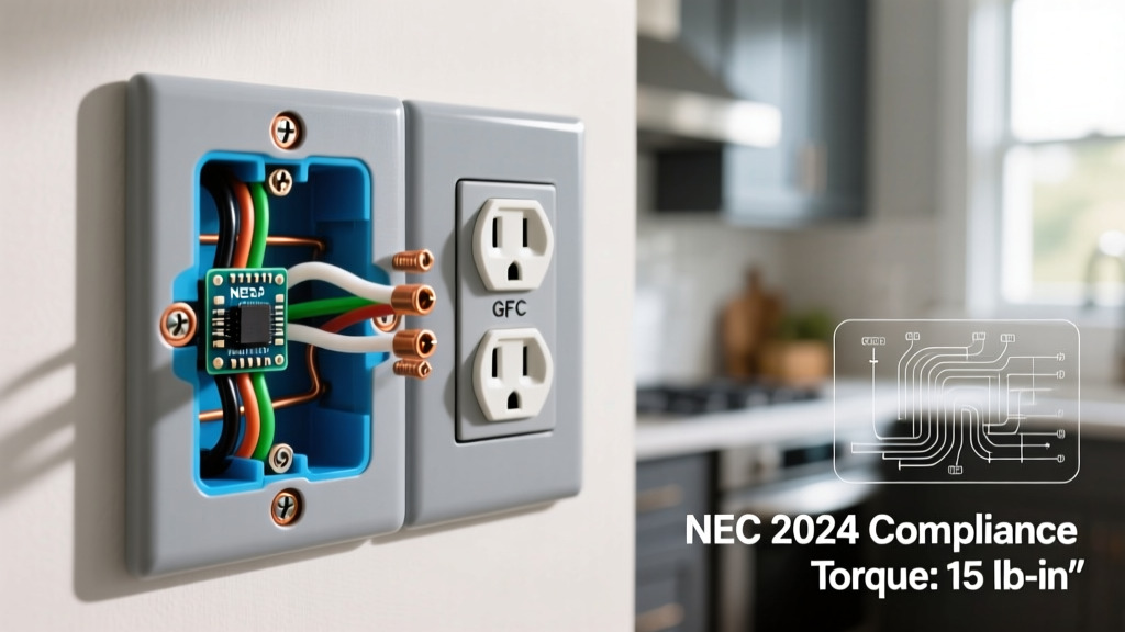

The Anatomy of an Electrical Outlet Safe for Modern Homes
When homeowners and DIYers ask, "Is my electrical outlet safe?", the answer rarely depends on the condition of the plastic faceplate. True safety is dictated by the internal wiring diagram, terminal torque specifications, and strict compliance with the National Electrical Code (NEC). In 2026, the baseline for residential receptacles has shifted dramatically from basic duplex outlets to advanced Tamper-Resistant (TR), Ground Fault Circuit Interrupter (GFCI), and Arc Fault Circuit Interrupter (AFCI) devices.
Making an electrical outlet safe requires moving beyond simple "black-to-brass, white-to-silver" color matching. It demands an understanding of continuous grounding paths, load-side feed-through protection, and mechanical termination limits. According to the Electrical Safety Foundation International (ESFI), improperly wired or degraded receptacles are a leading cause of residential electrical fires and shock hazards. This wiring diagram reference will break down the exact specifications required to ensure your installations meet modern safety thresholds.
NEC 2023/2026 Safety Mandates at a Glance
- NEC 406.12 (Tamper-Resistant): All 15A and 20A, 125V and 250V receptacles in dwelling units must be TR-rated to prevent foreign object insertion.
- NEC 210.8 (GFCI Protection): Mandatory for all 125V through 250V receptacles in bathrooms, kitchens, garages, crawlspaces, and outdoors.
- NEC 110.14(D) (Torque Specifications): Terminals must be tightened to the manufacturer's specified torque using a calibrated torque screwdriver.
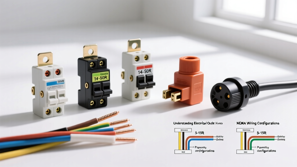
Wiring Diagram Reference: Standard 15A/20A TR Duplex Receptacles
For standard branch circuits, the most common device is the 15A Tamper-Resistant duplex receptacle (e.g., Leviton T5320-W). While the NEC allows "daisy-chaining" (wiring two cables directly to the four terminal screws on a single receptacle), this method compromises safety if the device is ever removed or fails internally. If the neutral wire relies on the receptacle's internal yoke to pass current downstream, removing the outlet breaks the neutral path for all downstream devices, creating a dangerous floating neutral scenario.
The Pigtail Method: The Gold Standard for Safety
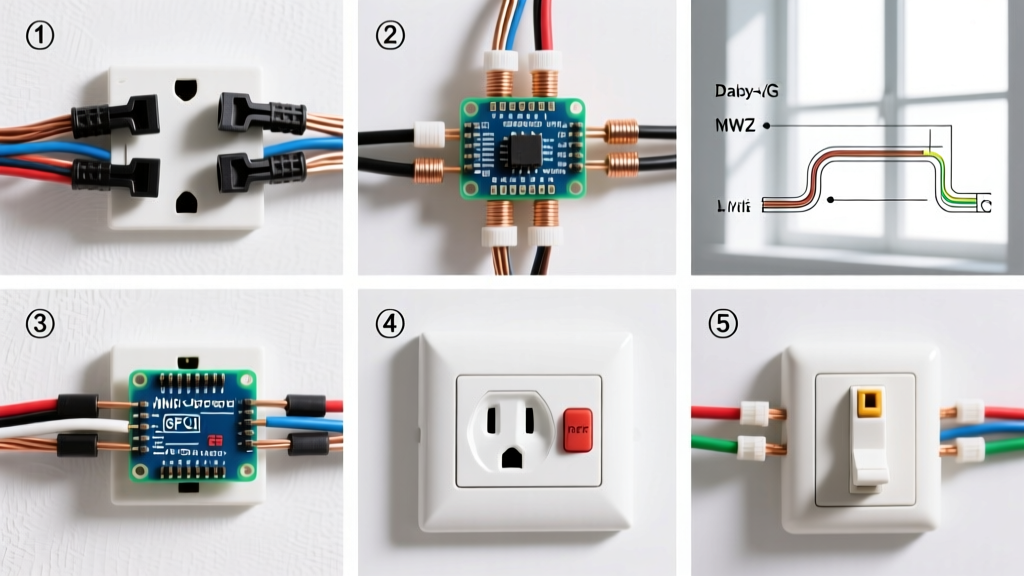
To keep your electrical outlet safe and maintain circuit continuity, always use the pigtail method. This involves connecting the incoming and outgoing wires together with a wire nut or push-in connector, and running a single short "pigtail" wire to the receptacle terminal.
- Strip Gauge: Use the built-in strip gauge on the back of the receptacle. For 14 AWG and 12 AWG solid copper wire, this is typically 5/8 inch (16mm). Exposing too much copper creates an arc-flash hazard; too little causes the screw to bite into the insulation, leading to high-resistance heating.
- Loop Direction: Form a J-hook in the wire and loop it clockwise around the terminal screw. As the screw tightens (clockwise), it will pull the loop tighter rather than pushing it out.
- Torque Application: NEC 110.14(D) requires verified torque. For most Leviton and Eaton 15A/20A residential TR receptacles, the manufacturer specifies 7 to 9 inch-pounds (in-lbs). Use a calibrated torque screwdriver (e.g., Klein Tools 32500) to click at the exact specification.
GFCI Protection: Line vs. Load Wiring Diagram Logic
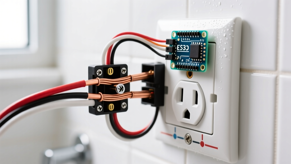
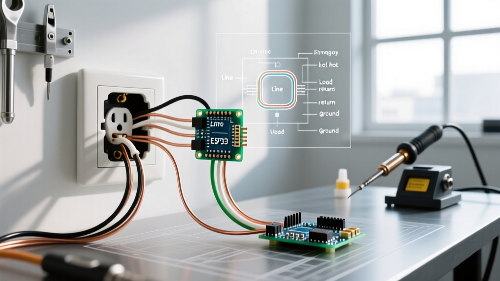
When wiring a GFCI receptacle (such as the Eaton GFTR15W), understanding the distinction between LINE and LOAD terminals is the difference between a functional safety device and a hidden hazard. The U.S. Consumer Product Safety Commission (CPSC) notes that miswired GFCIs fail to protect downstream outlets, leaving users vulnerable to lethal ground faults.
Identifying LINE vs. LOAD
- LINE Terminals: These connect to the incoming power source from the breaker panel. The hot (black) goes to the brass LINE screw, and the neutral (white) goes to the silver LINE screw.
- LOAD Terminals: These connect to downstream standard receptacles that you want to protect with this single GFCI device. The downstream hot goes to the brass LOAD screw, and the downstream neutral goes to the silver LOAD screw.
If you accidentally wire the incoming power to the LOAD terminals, the GFCI receptacle itself will still power on and function locally. However, the internal shunt-trip mechanism will be bypassed for downstream protection, and the device's internal diagnostics will fail to detect ground faults properly. Always use a non-contact voltage tester or multimeter to verify the incoming hot wire before connecting it to the LINE terminals.
Failure Modes: Why "Safe" Outlets Fail Prematurely
Even high-quality TR and GFCI receptacles can become dangerous if installation best practices are ignored. Below is a diagnostic matrix of common wiring failures, their root causes, and how to correct them based on National Fire Protection Association (NFPA) NEC 70 guidelines.
| Failure Mode | Root Cause | NEC Violation | Corrective Action |
|---|---|---|---|
| Thermal Melting at Terminals | Under-torqued screws causing high resistance and arcing. | 110.14(D) | Cut back damaged wire, re-strip, and torque to 7-9 in-lbs. |
| Backstabbed Push-In Failures | Using spring-loaded back-wire holes instead of side terminal screws. | 110.12 (Workmanlike Install) | Remove backstabbed wires; use side-binding screws or screw-clamp plates. |
| Floating Neutral Downstream | Daisy-chaining neutrals through the receptacle yoke instead of pigtailing. | 300.13 (Continuity) | Install a white pigtail wire nut connector to maintain neutral continuity. |
| GFCI Nuisance Tripping | Sharing a neutral between two different circuits (multi-wire branch circuit) on a standard GFCI. | 210.4 (MWBC) | Use a 2-pole GFCI breaker at the panel instead of a receptacle-level GFCI. |
Product Spotlight: Top TR & GFCI Receptacles for 2026 Upgrades
Selecting the right hardware is just as critical as the wiring diagram. Cheap, contractor-grade receptacles often feature inferior internal contacts that lose tension after a few years of plug insertion, leading to arcing. Here are the industry-standard models we recommend for ensuring long-term safety:
1. Leviton T5320-W (15A TR Duplex)
- Best For: Standard living rooms, bedrooms, and hallways.
- Price Range: $3.00 - $4.50 per unit.
- Key Feature: Heavy-duty thermoplastic construction with a patented TR shutter mechanism that requires simultaneous, equal pressure to open, completely defeating attempts by children to insert single objects like paperclips.
2. Eaton GFTR15W (15A GFCI TR)
- Best For: Kitchens, bathrooms, garages, and outdoor wet locations.
- Price Range: $20.00 - $26.00 per unit.
- Key Feature: Features an auto-monitoring function that periodically tests its own ground-fault protection circuit. If the internal protection is compromised, the device automatically denies power and illuminates a red LED, preventing a false sense of security.
Verification: Testing Your Electrical Outlet Safe Installation
Once the wiring is complete and the cover plate is installed, visual inspection is not enough. You must electrically verify the installation. While cheap $10 plug-in testers with three neon lights are common, they often fail to detect "bootleg grounds" (where a jumper wire is illegally installed between the neutral and ground terminals to trick the tester).
For professional-grade verification, use a solenoid-based tester or an advanced digital diagnostic tool like the Klein Tools RT250 ($45.00). The RT250 uses a high-impedance digital circuit to detect reverse polarity, open grounds, and open neutrals without relying on the grounding pin's physical connection to the panel. Furthermore, when testing a GFCI, do not just rely on the built-in "TEST" button on the faceplate. Use the GFCI test function on your plug-in tester to verify that the internal shunt trip activates correctly from a downstream perspective, ensuring the entire circuit is protected as intended by your wiring diagram.
Final Safety Checklist
- [ ] All bare copper ground wires are securely bonded to the metal box (if applicable) and the receptacle's green grounding screw.
- [ ] No exposed copper is visible outside the terminal connection points.
- [ ] The receptacle sits flush against the wall without requiring the cover plate to force it into position (use box extenders or shims if the box is recessed more than 1/4 inch).
- [ ] Torque screwdriver clicked at the manufacturer's specified inch-pound rating.
By adhering to these wiring diagrams, torque specifications, and NEC mandates, you transition from simply "making connections" to engineering a robust, fault-tolerant system. Whether you are upgrading a single kitchen counter circuit or rewiring an entire floor, these principles guarantee that every electrical outlet safe for your family and compliant with modern codes.