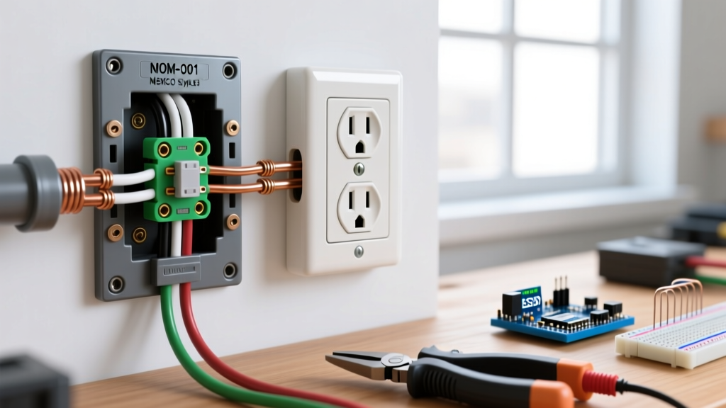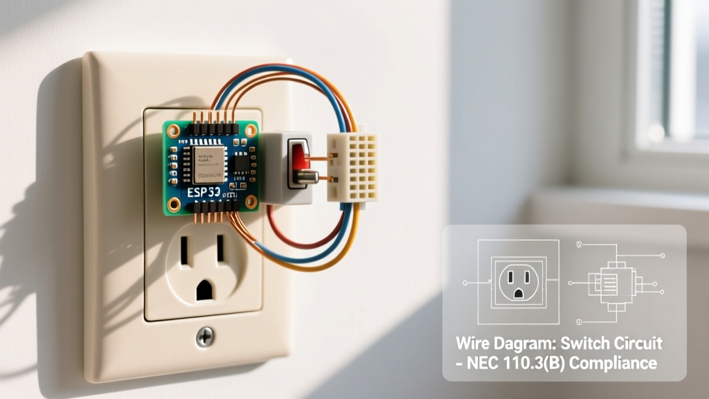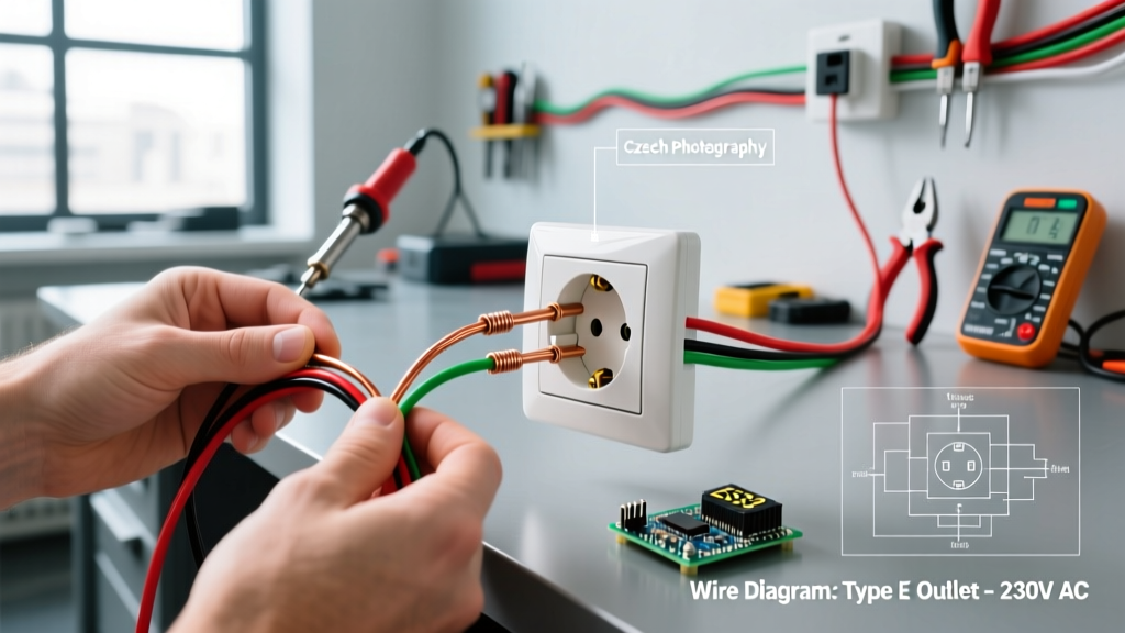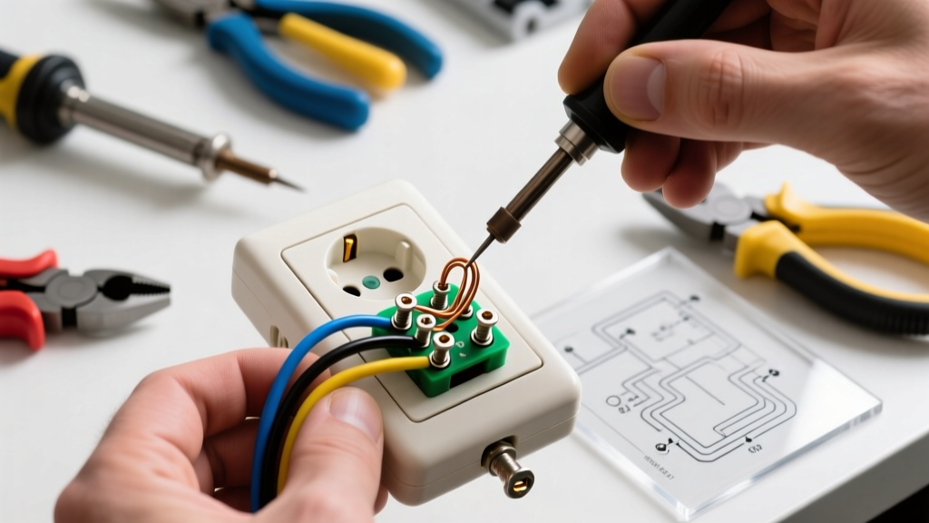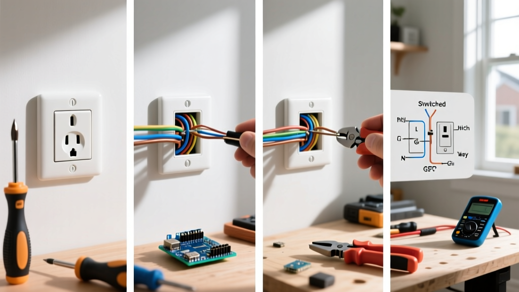

Why Upgrade Your Standard Duplex Receptacle?
When it comes to changing an electrical outlet, the difference between a safe, code-compliant installation and a hidden fire hazard often comes down to millimeter-level precision and proper torque. While a standard 15-amp duplex receptacle might seem like a trivial component, it is the primary mechanical and electrical interface between your home's branch circuit and your appliances.
As of 2026, the National Electrical Code (NEC) mandates Tamper-Resistant (TR) receptacles in virtually all residential living spaces. Furthermore, the increasing continuous power draw from modern high-wattage electronics and smart home hubs means that builder-grade, 50-cent receptacles are failing prematurely due to thermal fatigue. Upgrading to a commercial-specification TR receptacle, such as the Leviton 5262-R or Hubbell 5262-R, provides heavier brass contacts, superior clamping force, and a longer operational lifespan.
Tools, Materials, and Cost Breakdown
Professional-grade tools ensure safety and compliance. Do not rely on worn-out flathead screwdrivers or uncalibrated wire strippers when working with live panels or branch circuits.
| Item | Recommended Model / Spec | Estimated Cost (2026) | Purpose |
|---|---|---|---|
| TR Receptacle | Leviton 5262-R (Commercial Grade, 15A/125V) | $3.50 - $4.50 | Primary replacement component |
| Voltage Tester | Klein Tools NCVT-2 (Dual-Range NCVT) | $28.00 | Initial live/dead verification |
| Wire Strippers | Klein 11055 (10-20 AWG Solid/Stranded) | $24.00 | Preventing copper scoring during prep |
| Torque Screwdriver | CDI 401SM (10-50 in-lbs) or Klein 32500 | $45.00 - $120.00 | NEC 110.14(D) compliance |
| Insulated Drivers | Wiha 32090 Insulated Set (1000V rated) | $35.00 | Arc flash and shock protection |
Critical Safety Pre-Check: Identifying MWBCs
Before you unscrew the faceplate, you must rule out a Multi-Wire Branch Circuit (MWBC). An MWBC shares a single neutral wire between two hot wires (typically one black, one red) on opposite phases. If you disconnect the neutral while the circuit is energized, or if you only turn off one of the two breakers, the shared neutral can carry the sum of both circuits' current, leading to melted insulation, severe shock, or fire.
WARNING: If you open the existing outlet and see both a red and a black wire connected to the brass (hot) terminals, you are dealing with an MWBC. You must locate both corresponding breakers in your panel and turn them off simultaneously. Under current NEC guidelines, these breakers must be equipped with an approved handle tie or be a single double-pole breaker to ensure simultaneous disconnect.
Step-by-Step Installation Procedure
Step 1: Power Verification and Removal
- Test Before Touch: Use your Klein NCVT-2 to scan the faceplate screws and the receptacle slots. The tester should remain dark and silent.
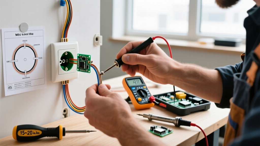
- Cross-Check with a Multimeter: NCVTs can be fooled by phantom voltage or thick drywall. Insert the probes of a digital multimeter into the top and bottom slots (hot to neutral, hot to ground) to verify 0.0V.
- Extract the Yoke: Remove the top and bottom 6-32 mounting screws. Gently pull the receptacle out of the gang box, being careful not to stress the wires.
Step 2: Wire Inspection and Preparation
Examine the existing copper conductors. If the wires were previously backstabbed (pushed into the rear holes of the old outlet), you will likely find deep scoring or pitting on the copper. Use your wire strippers to snip off the damaged ends and re-strip the wire.
Use the strip gauge located on the back of the new Leviton or Hubbell receptacle. For 14 AWG wire, the strip length is typically 5/8 inch; for 12 AWG, it is often 3/4 inch. Stripping too little insulation leaves the plastic jacket caught under the terminal screw, creating a high-resistance connection. Stripping too much leaves bare, exposed copper outside the terminal, posing a short-circuit risk.
Step 3: The Side-Wire Method (Never Backstab)
While modern push-in backwire clamps (found on premium commercial outlets) are UL-listed and reliable, the cheap friction-based backstab holes found on residential-grade outlets are a primary cause of electrical fires. Thermal imaging studies consistently show backstabbed connections running 40°F to 60°F hotter than side-wired screw terminals under continuous load.
- Form the Shepherd's Hook: Use needle-nose pliers to bend the stripped copper into a tight, 270-degree hook.
- Clockwise Wrapping: Loop the wire around the terminal screw clockwise. This ensures that as you tighten the screw (which turns clockwise), the loop pulls tighter rather than splaying outward.
- Seat the Wire: Ensure the wire enters the terminal from the left, wraps under the screw head, and exits to the right. The insulation should sit flush against the metal yoke, with no bare copper visible outside the pressure plate.
Step 4: Torque to NEC Specifications
Since the 2017 NEC update, and strictly enforced through 2026, NEC 110.14(D) requires that all electrical connections be torqued to the manufacturer's specified values using a calibrated torque tool. Hand-tightening is no longer acceptable for new installations or replacements.
For a standard 15A or 20A commercial receptacle using 12 AWG solid copper wire, the manufacturer typically specifies 14 in-lbs of torque. Set your torque screwdriver, tighten the terminal until the tool clicks, and stop immediately. Overtorquing can strip the brass threads or snap the screw head, while undertorquing leads to thermal expansion cycles that eventually loosen the connection and cause arcing.
Grounding and Pigtailing Best Practices
Never use the receptacle's internal yoke as the sole path for the equipment grounding conductor (EGC) to downstream outlets. If the receptacle fails or is removed, the ground path for all downstream devices is broken. Always use a wire nut or a Wago 221-series lever connector to pigtail the bare copper ground wires, attaching a single 6-inch pigtail directly to the green grounding screw on the new receptacle. This ensures a continuous, uninterrupted ground fault path back to the panel.
Troubleshooting Edge Cases and Failure Modes
After securing the receptacle to the gang box and installing the faceplate, restore power and test with a plug-in circuit analyzer. If the tester indicates a fault, refer to this diagnostic matrix:
- Open Ground: The bare copper wire is loose, disconnected at the panel, or you forgot to attach the pigtail to the green screw. Fix: Verify continuity to the panel ground bus.
- Reversed Polarity: The white (neutral) wire is on the brass (hot) screw, and the black (hot) wire is on the silver (neutral) screw. This leaves the appliance energized even when switched off. Fix: Swap the hot and neutral connections.
- Hot/Neutral Reverse with Open Ground: Often indicates a "bootleg ground" left by a previous DIYer, where the neutral and ground were jumpered together to trick a tester. This is extremely dangerous and violates NEC 250.148. Fix: Remove the jumper and properly route a new EGC or install a GFCI receptacle labeled "No Equipment Ground" per NEC 406.4(D).
Authoritative References and Code Standards
Electrical work must always align with current safety standards and empirical data. The procedures outlined in this guide are based on the following authoritative resources:
- National Fire Protection Association (NFPA) - Electrical Safety Guidelines: Provides critical data on home electrical fires and the importance of proper torque and connection integrity.
- U.S. Consumer Product Safety Commission (CPSC) - Outlet Safety: Details the life-saving statistics behind Tamper-Resistant (TR) receptacles and the hazards of worn-out contacts.
- Electrical Safety Foundation International (ESFI) - Tamper-Resistant Receptacles: Offers in-depth technical explanations of TR shutter mechanisms and NEC adoption timelines.
By adhering to these precise steps, utilizing commercial-grade components, and respecting torque specifications, you ensure that your newly installed receptacle will provide safe, reliable power for decades to come.