
Why Upgrade Your Electrical Outlets?
Upgrading aging, discolored, or loose electrical receptacles is one of the highest-impact safety improvements you can make in any residential or commercial space. Over time, the internal metal contacts of a receptacle lose their tension, leading to arcing, excessive heat, and potentially electrical fires. Furthermore, modern electrical codes have evolved significantly. If your home was built before 2008, it likely lacks Tamper-Resistant Receptacles (TRRs), which are now mandated by the National Electrical Code (NEC) to prevent childhood shock injuries.
This comprehensive guide will walk you through exactly how to install an electrical outlet, focusing on modern upgrades like TRRs, GFCIs, and integrated USB-C receptacles, while adhering to strict 2026 safety standards.
The 15A vs. 20A Circuit Dilemma
Before purchasing replacement receptacles, you must identify your circuit's amperage. A common and dangerous mistake is installing a 20-amp receptacle on a 15-amp circuit.
- 15-Amp Circuits (14 AWG Wire): Use standard 15A receptacles (NEMA 5-15R). You cannot install a 20A receptacle here.
- 20-Amp Circuits (12 AWG Wire): You can install either 20A receptacles (NEMA 5-20R, featuring a T-shaped neutral slot) or 15A receptacles. NEC Article 210.21(B)(3) explicitly allows multiple 15A receptacles on a single 20A circuit, as no single plug-in device will draw the full 20 amps.
Pro Tip: Check the breaker in your main panel. If it says '15', buy 15A receptacles. If it says '20', you have the flexibility to upgrade to 20A receptacles for high-draw appliances like kitchen mixers or heavy-duty power tools.
Receptacle Selection Matrix: 2026 Upgrade Options
Not all outlets are created equal. Below is a comparison of modern receptacle types suitable for residential upgrades.
| Receptacle Type | Recommended Model | Avg. Cost | Best Application |
|---|---|---|---|
| Standard 15A TRR | Leviton T52-R (Residential Grade) | $2.50 - $3.50 | Bedrooms, living rooms, hallways |
| Commercial 15A TRR | Leviton 5262-SW (Spec Grade) | $4.50 - $6.00 | High-traffic areas, home offices |
| Self-Test GFCI | Leviton GFNT2-W | $18.00 - $22.00 | Kitchens, bathrooms, garages, exteriors |
| USB-C / USB-A Combo | Leviton U5600-W (USB-C PD) | $32.00 - $38.00 | Kitchen islands, bedside tables, workshops |
Tools and Materials Required
To ensure a code-compliant and safe installation, gather the following professional-grade tools:
- Non-Contact Voltage Tester: Klein Tools NCVT-3 (essential for verifying dead circuits).
- Wire Strippers: Klein Tools 11048 (specifically calibrated for 12 and 14 AWG solid copper).
- Screwdrivers: Insulated Phillips and Flathead (#2 tip).
- Torque Screwdriver: CDI 401SM or similar, calibrated to inch-pounds.
- Receptacle: UL-listed, Tamper-Resistant (TRR marked).
- Wire Nuts / Connectors: Ideal Wing-Nut 341 or WAGO 221 series lever nuts for pigtailing.
Step-by-Step: How to Install an Electrical Outlet
Step 1: Kill the Power and Verify
Turn off the corresponding circuit breaker at the main panel. Insert a non-contact voltage tester into both the top and bottom slots of the existing receptacle. The tester must remain completely dark and silent. Never assume a breaker label is accurate.
Step 2: Remove the Old Receptacle
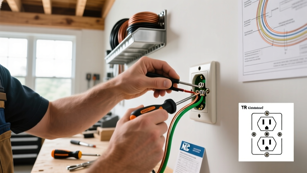
Unscrew the faceplate and the top/bottom mounting screws holding the receptacle to the electrical box. Gently pull the device out. Take a photo of the existing wiring configuration before disconnecting anything.
Step 3: Inspect the Wiring and Box
Look closely at the exposed copper wire. If the wire is dull gray, you have aluminum wiring (common in homes built between 1965 and 1972). Standard brass-terminal receptacles will cause a galvanic reaction with aluminum, leading to overheating and fire. You must use CO/ALR rated receptacles or pigtail the aluminum to copper using AlumiConn lug connectors.
Step 4: Strip and Prepare the Wires
Cut off the old stripped ends, as they may be oxidized or fatigued from previous bending. Use your wire strippers to remove exactly 3/4 inch of insulation for side-wiring, or strip to the specific gauge mark indicated on the back of the new receptacle for back-wiring.
⚠️ Critical Warning: Avoid Push-In 'Backstab' Connections
Many cheap receptacles feature push-in holes on the back. These rely on a tiny spring-metal wedge to hold the wire. Due to thermal expansion and contraction during normal use, these connections frequently loosen over time, causing arcing. Always use the side screw terminals or the screw-clamp back-wiring plates found on commercial-grade receptacles.
Step 5: Make the Connections
Follow the standard color-coding:
- Ground (Bare Copper or Green): Connect to the green grounding screw at the bottom of the receptacle.
- Neutral (White): Connect to the silver-colored screws. Ensure the wire loops clockwise around the screw so that tightening the screw pulls the loop closed, rather than pushing it out.
- Hot (Black or Red): Connect to the brass-colored screws.
Step 6: Torque to Specification
Modern electrical codes and manufacturer instructions require specific torque values for terminal screws to prevent loose connections. According to NEC 110.14(D), equipment marked with torque values must be tightened accordingly. For most Leviton and Eaton 15A/20A residential and commercial receptacles, the specified torque is 14 in-lbs. Use a calibrated torque screwdriver to achieve this exact spec.
Step 7: Mount and Test
Carefully fold the wires into the back of the electrical box using a 'Z' fold pattern to avoid pinching the ground wire against the device strap. Secure the receptacle with the provided mounting screws. Attach the faceplate, restore power at the breaker, and test with a 3-light receptacle tester (like the Sperry Instruments ET6420) to confirm correct wiring.
Troubleshooting Common Installation Failures
Even experienced DIYers encounter issues during outlet replacement. Here is how to diagnose the most common failures:
Reversed Polarity (Hot and Neutral Swapped)
Symptom: Your 3-light tester shows a red/yellow 'Reverse Polarity' indication. Fix: The black (hot) wire is on the silver screw, and the white (neutral) is on the brass screw. Turn off the power, swap the wires, and retest. This is a severe shock hazard, as the outer sleeve of a plugged-in lamp will remain energized even when the lamp switch is off.
Open Ground
Symptom: Tester indicates 'Open Ground' (yellow/green lights). Fix: The bare copper ground wire is either disconnected, broken inside the wall, or not bonded to the metal electrical box. If you are in an older home with no ground wire present in the box, NEC 406.4(D) allows you to install a GFCI receptacle and label it 'No Equipment Ground', providing shock protection without a physical ground path.
GFCI Trips Immediately
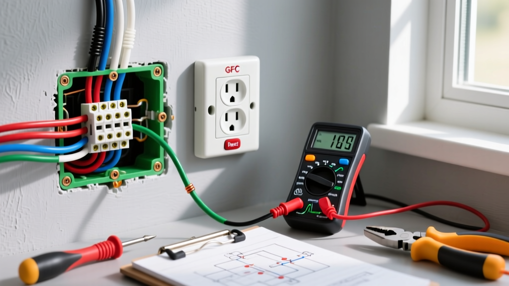
Symptom: Newly installed GFCI outlet will not reset. Fix: You likely connected the downstream wires to the 'LINE' terminals instead of the 'LOAD' terminals, or there is a ground fault further down the circuit. Ensure the wires coming directly from the breaker panel are on the LINE terminals. Use a multimeter to check for continuity between the neutral and ground on the LOAD side to find the downstream fault.
Expert Insights on Tamper-Resistant Receptacles (TRRs)
'Tamper-Resistant Receptacles are equipped with internal shutters that block foreign objects from being inserted into the slots. According to the Consumer Product Safety Commission (CPSC), these shutters only open when equal pressure is applied to both slots simultaneously, as happens when inserting a standard plug. They are a critical defense against pediatric electrical burns.'
When installing TRRs, you may notice that plugs require slightly more insertion force initially. This is normal. Do not attempt to file down the shutters or force a plug in at an angle, as this can damage the internal mechanism and void the UL listing.
Final Thoughts on Electrical Safety
Learning how to install an electrical outlet is a foundational DIY skill, but it requires strict adherence to safety protocols and current NEC standards. Upgrading to commercial-grade TRRs, utilizing torque screwdrivers, and abandoning push-in backstab connections will ensure your electrical system remains safe, reliable, and code-compliant for decades. For further reading on residential electrical safety practices, consult the Electrical Safety Foundation International (ESFI) resources before tackling complex multi-wire branch circuits or panel upgrades.