
Understanding the Standard Electric Outlet
When homeowners and DIY enthusiasts refer to a standard electric outlet, they are typically talking about a 15-amp, 125-volt duplex receptacle (NEMA 5-15R). This is the most common electrical connection point in residential buildings across North America, powering everything from lamps to televisions. However, installing or replacing one requires a strict adherence to safety protocols and modern electrical codes.
15A vs. 20A Receptacles: Knowing the Difference
Before purchasing materials, you must identify your circuit's amperage. A standard 15-amp circuit uses 14 AWG (American Wire Gauge) copper wire and requires a 15A receptacle. A 20-amp circuit uses thicker 12 AWG wire and can accept either a 20A receptacle (NEMA 5-20R, which features a T-shaped neutral slot) or a standard 15A duplex receptacle. Never install a 20A receptacle on a 15A circuit, and never use 14 AWG wire on a 20-amp breaker.
Essential Tools and Materials for 2026
Professional electricians rely on specific, high-quality tools to ensure connections are safe and long-lasting. Here is the exact gear you need for a standard electric outlet installation, along with current market pricing:
- Receptacle: Leviton 5262 (15A, 125V, Duplex, Self-Grounding) — Approx. $1.50 to $2.50 each.
- Wire Strippers: Klein Tools 11055 (10-20 AWG Solid) — Approx. $28.00.
- Lineman Pliers: Klein Tools 2000N (High-Leverage) — Approx. $35.00.
- Non-Contact Voltage Tester: Fluke 2AC-II VoltAlert — Approx. $30.00.
- Torque Screwdriver: Milwaukee 48-22-2804 (10-50 in-lbs) — Approx. $110.00 (Crucial for modern NEC compliance).
- Wire Connectors: Ideal Wire-Nut 341 (Tan, for 14 AWG pigtailing) — Approx. $8.00 for a box of 100.
Pre-Installation Safety Protocol
Electrical work is unforgiving of mistakes. According to the National Fire Protection Association (NFPA), electrical failures or malfunctions are a leading cause of home fires. Never skip the verification steps.
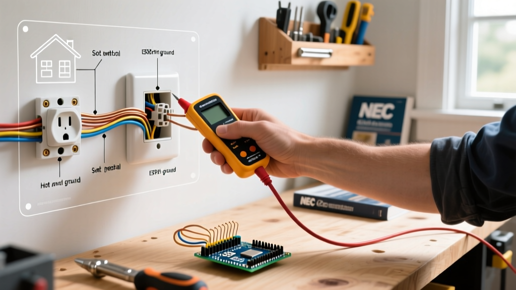
Critical Safety Warning: Always turn off the power at the main circuit breaker panel before opening any electrical box. Use a non-contact voltage tester to verify the power is off at the outlet, and test the tester on a known live circuit first to ensure its battery is functioning.
Furthermore, the Consumer Product Safety Commission (CPSC) recommends replacing any outlets that feel warm to the touch, show signs of discoloration, or have loose-fitting plugs, as these are prime indicators of internal arcing and fire hazards.
Step-by-Step Installation Guide
Follow this precise sequence to wire your standard electric outlet safely and effectively.
Step 1: Prepare the Wires
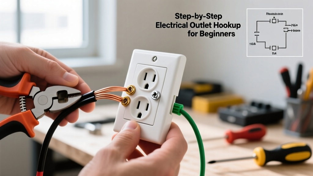
Using your Klein 11055 wire strippers, remove exactly 3/4 inch of insulation from the black (hot), white (neutral), and bare copper (ground) wires. Stripping too little will result in the screw head resting on the insulation, causing a high-resistance connection. Stripping too much will leave exposed, uninsulated copper outside the terminal, creating a shock hazard.
Step 2: Create Pigtails (Recommended Method)
While you can "daisy-chain" power through the outlet to the next box, professional electricians prefer pigtailing. This involves connecting the incoming and outgoing wires together with a short 6-inch piece of matching wire (the pigtail) using a wire nut, and then attaching only the pigtail to the receptacle. This ensures that if the outlet fails or is removed, downstream outlets do not lose power.
Step 3: Form the J-Hooks
Using the needle-nose section of your pliers, bend the stripped end of each pigtail into a smooth "J-hook" or "shepherd's hook". The curve should match the diameter of the terminal screw.
Step 4: Attach to the Terminals
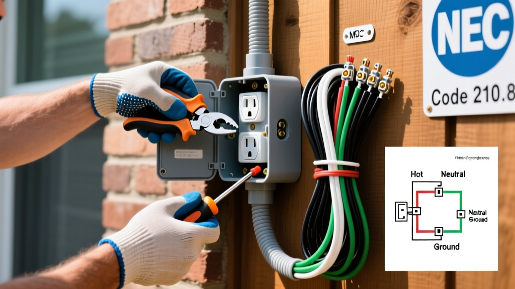
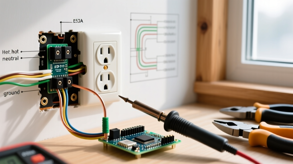
Hook the wires onto the brass and silver screws in a clockwise direction. This ensures that as you tighten the screw (which turns clockwise), the loop closes tighter around the screw shaft rather than being pushed outward. Follow this color code:
- Black (Hot) Pigtail: Attach to the brass-colored screw.
- White (Neutral) Pigtail: Attach to the silver-colored screw.
- Bare Copper (Ground) Pigtail: Attach to the green grounding screw.
Step 5: Apply Exact Torque
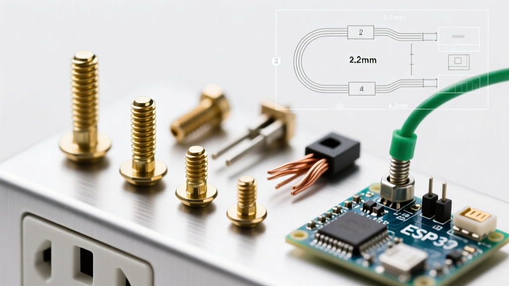
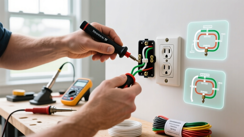
Modern electrical codes strictly mandate the use of calibrated torque tools. Hand-tightening is no longer acceptable for new installations. Set your torque screwdriver to the manufacturer's specification (usually found on the back of the receptacle or in the spec sheet) and tighten until the tool clicks.
Torque Specifications (NEC Compliance)
The National Electrical Code (NEC) Section 110.14(D) requires that connections be torqued to the manufacturer's specified values. Under-torquing leads to loose connections, which generate immense heat through electrical resistance. Over-torquing can strip the threads or snap the screw head. Below are standard torque values for a typical 15A Leviton receptacle:
| Wire Gauge | Wire Material | Terminal Type | Required Torque (in-lbs) |
|---|---|---|---|
| 14 AWG | Copper | Brass/Silver Screw | 14 in-lbs |
| 12 AWG | Copper | Brass/Silver Screw | 14 in-lbs |
| 14-10 AWG | Copper | Green Ground Screw | 14 in-lbs |
Note: Always defer to the specific torque values printed on the device packaging or the manufacturer's official specification sheet if they differ from the chart above.
Common Beginner Mistakes to Avoid
Even with the right tools, beginners often fall into bad habits that compromise the safety of the standard electric outlet. Avoid these critical errors:
- Using the "Back-Stab" Push-In Terminals: Many cheap receptacles feature small holes on the back where you can simply push the stripped wire in without using a screwdriver. Never use these. They rely on a tiny internal spring clip that loses tension over time, leading to arcing and fires. Always use the side-wire terminal screws or the screw-clamp back-wiring plates found on higher-grade commercial outlets.
- Reversing Polarity: Connecting the black hot wire to the silver screw and the white neutral to the brass screw is a severe shock hazard. The internal switch mechanism of appliances expects the hot wire on the brass side.
- Overcrowding the Box: If you are pigtailing multiple wires, ensure your electrical box has adequate cubic inch capacity. A standard single-gang plastic box (approx. 18-22 cubic inches) is usually sufficient, but if you are adding smart outlets or bulky dimmers, you may need a deep 22.5 cubic inch box to meet NEC box-fill calculations.
- Breaking the Wrong Fin: Standard duplex outlets have a small metal tab (fin) connecting the top and bottom brass screws, and another connecting the silver screws. If you are wiring a standard outlet, leave both intact. Only break the brass fin if you are creating a "split-receptacle" (where one half is controlled by a wall switch and the other is always hot).
Testing and Verification
Once the outlet is secured to the box and the faceplate is installed, restore power at the breaker panel. Do not rely solely on plugging in a lamp to test the circuit.
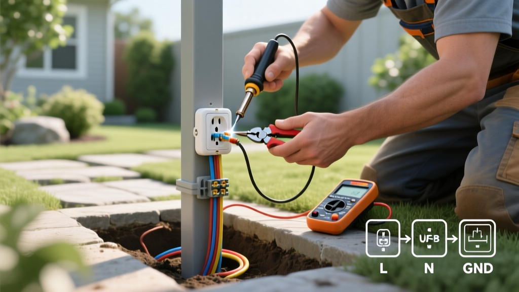
Use a dedicated receptacle tester (such as the Gardner Bender GRT-901, approx. $12.00). Plug it into the newly installed standard electric outlet and observe the LED light pattern. A correct wiring pattern will illuminate two yellow lights. If the tester indicates "Open Ground," "Reverse Polarity," or "Hot/Neutral Reverse," turn the breaker back off immediately and re-inspect your terminal connections.
For further safety standards regarding electrical installations and workplace safety protocols, refer to the Occupational Safety and Health Administration (OSHA) electrical guidelines, which provide excellent foundational knowledge on lockout/tagout procedures and hazard recognition.
Frequently Asked Questions
Can I replace a two-prong outlet with a standard three-prong outlet?
Only if there is an actual equipment grounding path (like a bare copper wire or metallic conduit) in the box. If your home has older, ungrounded wiring (Knob-and-Tube or early Romex without a ground wire), you cannot legally install a standard grounded 3-prong outlet. You must either install a GFCI receptacle (labeled "No Equipment Ground") or run new grounded cable from the panel.
Why does my outlet feel warm?
A standard electric outlet should never feel warm to the touch. Warmth indicates high electrical resistance, usually caused by a loose terminal screw, degraded back-stab connections, or an overloaded circuit drawing near its maximum amperage continuously. Turn off the breaker and inspect the wiring immediately.