
Why Install a Freestanding Outdoor Receptacle?
Running power to the middle of your yard, driveway, or garden bed often requires more than just an extension cord. An outdoor electrical outlet post (also known as a yard pedestal or freestanding receptacle column) provides a permanent, code-compliant, and weatherproof power source exactly where you need it. Whether you are powering landscape lighting, pond pumps, holiday inflatables, or even a future electric vehicle charger at the end of your driveway, a dedicated post eliminates trip hazards and voltage drop issues associated with long extension cords.
For beginners, the prospect of digging trenches and wiring a GFCI-protected outdoor circuit can seem daunting. However, by breaking the project down into manageable phases and adhering to modern safety standards, this installation is well within the reach of a careful DIYer. In this comprehensive 2026 guide, we will walk you through the exact materials, trenching depths, and wiring matrices required to install a heavy-duty cast aluminum outlet post safely.
Materials and Tool Checklist
Using the right materials is non-negotiable for outdoor electrical work. Standard indoor NM-B (Romex) wire will degrade rapidly when exposed to moisture and soil. You must use direct-burial rated cables and weatherproof enclosures.
| Item | Recommended Specification / Model | Estimated Cost |
|---|---|---|
| Pedestal Post | Raco 635-0 Cast Aluminum Yard Post (36-inch) | $85 - $110 |
| Wire | Southwire 12/2 UF-B (Underground Feeder) - 50ft | $45 - $60 |
| GFCI Receptacle | Leviton 8599-W 20-Amp Weather-Resistant GFCI | $22 - $28 |
| Weatherproof Cover | TayMac MX1000 Extra-Duty In-Use Cover | $14 - $18 |
| Conduit & Fittings | Carlon 1/2-inch PVC Schedule 40 & Sweep 90 | $15 - $20 |
| Concrete | Quikrete Fast-Setting Concrete Mix (50 lb bag) | $6 - $8 |
Note: Prices reflect average national retail pricing as of early 2026. Local hardware store availability may vary.
Phase 1: Site Planning and Safety Protocols
Before you put a shovel in the dirt, you must address two critical safety and legal requirements.
1. Call 811 (Utility Locating)
Striking a buried gas, water, or fiber-optic line can be fatal and financially ruinous. In the United States, calling 811 is a free, legally mandated step before any excavation. According to the Call 811 national portal, you must notify your local utility locating service at least 2 to 3 business days before digging. They will mark public utility lines with paint and flags at no cost to you. Remember that private lines (like sprinkler systems or invisible dog fences) will not be marked by 811 and must be located manually.
2. Understand NEC Trench Depth Requirements
The National Electrical Code (NEC) strictly governs how deep underground cables must be buried to prevent accidental damage from shovels or aerators. According to the National Fire Protection Association (NFPA), which publishes the NEC, the minimum cover requirements for a standard 120V residential circuit are:
- 24 inches deep for direct-burial UF-B cable.
- 18 inches deep if the UF-B cable is sleeved in rigid metal or Schedule 80 PVC conduit for its entire length.
- 12 inches deep if you use PVC conduit with a GFCI-protected circuit (though 18 inches remains the best practice for future-proofing and physical protection).
For this beginner tutorial, we will use the 24-inch direct burial method for the UF-B cable, transitioning to PVC conduit only where the cable exits the ground and enters the post.
Phase 2: Step-by-Step Installation Guide
Step 1: Trenching and Conduit Transition
Dig a trench from your power source (typically an existing indoor basement circuit or a garage subpanel) to the desired post location. The trench must be a consistent 24 inches deep. At the base of the post location, glue a 1/2-inch PVC Schedule 40 sweep 90-degree elbow pointing upward. The UF-B cable will run through the dirt and enter the bottom of this PVC elbow, protecting the wire from moisture and physical stress exactly at the ground-to-air transition point. The PVC pipe should extend up into the hollow base of the aluminum post by at least 6 inches.
Step 2: Securing the Pedestal Base
A cast aluminum post like the Raco 635-0 is heavy and acts as a lever in high winds; it must be anchored properly. You have two options:
- Concrete Footing (Recommended): Dig a hole 12 inches wide and 24 inches deep at the post location. Place the post base in the hole, use a level to ensure it is perfectly plumb, and pour a 50 lb bag of Quikrete Fast-Setting Concrete around it. Allow 24 hours to cure before pulling wire.
- Earth Anchor Spike: For softer soils, some pedestals include a 24-inch steel ground spike. Drive the spike into the earth using a sledgehammer, then bolt the post to the spike head. This is faster but less stable in frost-heave regions.
Step 3: Pulling the UF-B Cable
Feed the 12/2 UF-B cable through the trench and up through the PVC conduit into the post's wiring compartment. Leave at least 12 inches of slack inside the post for stripping and wiring. Backfill the trench, tamping the soil every 6 inches to prevent future sinking. Lay a strip of bright red 'Caution: Buried Electric Line' warning tape about 12 inches below the final grade level to warn anyone digging in the future.
Step 4: GFCI Receptacle Wiring
Modern electrical codes require Ground Fault Circuit Interrupter (GFCI) protection for all outdoor receptacles. The U.S. Consumer Product Safety Commission (CPSC) notes that GFCIs prevent severe shocks by detecting imbalances in current as small as 4 to 6 milliamps, shutting off power in a fraction of a second.
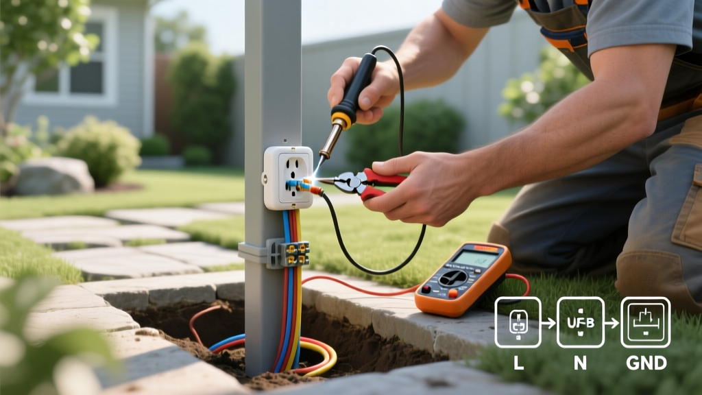
Strip 3/4 inch of insulation from the black (hot), white (neutral), and bare (ground) wires. Connect the bare copper ground wire to the green grounding screw on the GFCI receptacle and to the green grounding screw inside the cast aluminum post itself to bond the metal enclosure.
Terminal Wiring Matrix: Line vs. Load
The most common beginner mistake when wiring a GFCI is confusing the LINE and LOAD terminals. If wired backward, the outlet will have power, but it will not provide shock protection, and the 'Test' button will not function.
| Terminal Label | Function | Wire Connection |
|---|---|---|
| LINE | Receives incoming power from the breaker panel. | Connect the black and white wires coming from the house/trench here. |
| LOAD | Sends protected power downstream to other outlets. | Leave these empty unless you are daisy-chaining a second post. Cap any exposed wire. |
| GROUND | Provides a safe path for fault currents. | Connect bare copper to the receptacle's green screw AND the metal post's grounding lug. |
Phase 3: Sealing and Weatherproofing
Once the wires are secured and the GFCI is mounted to the post's faceplate, install the TayMac MX1000 Extra-Duty In-Use cover. This cover is deep enough to accommodate bulky outdoor plugs (like transformer blocks for holiday lights) while keeping the lid closed.
Pro-Tip for Moisture Ingress: Before tightening the faceplate screws, run a bead of clear, outdoor-rated silicone caulk around the top and side edges of the cover plate where it meets the aluminum post. Leave the bottom edge uncaulked. This allows any internal condensation to drain out (weeping) while preventing rain from driving in from above.
Common Edge Cases and Troubleshooting
Even with careful installation, outdoor environments present unique challenges. Here is how to handle common edge cases:
- Nuisance Tripping: If your GFCI trips frequently during heavy rain or snow, moisture is likely entering the enclosure. Check that the in-use cover's rubber gasket is fully seated and that the silicone seal on the top edges is intact. Ensure the UF-B cable jacket extends fully into the PVC conduit and isn't exposing individual wire insulation to condensation.
- Voltage Drop Over Long Distances: If your post is more than 100 feet from the breaker panel, a 12-gauge wire may experience voltage drop, causing motors (like pond pumps) to overheat. In runs exceeding 100 feet, upgrade to 10/2 UF-B cable to maintain a solid 120V at the receptacle.
- Frost Heave Shifting: In northern climates, freezing soil can push concrete footings upward. To prevent this, ensure your concrete footing is poured below the local frost line (often 36 to 48 inches deep in northern zones), or use a sonotube to create a smooth concrete pillar that the frost cannot grip.
Final Inspection and Power On
Before backfilling the final inches of soil or turning the breaker on, double-check all terminal screws for tightness. A loose neutral wire will cause arcing and melt the receptacle. Once satisfied, turn the breaker on. Press the 'Test' button on the GFCI; it should click and cut power. Press 'Reset' to restore power. Plug in a simple receptacle tester to verify correct wiring and GFCI functionality. Your outdoor electrical outlet post is now ready for years of safe, weatherproof service.