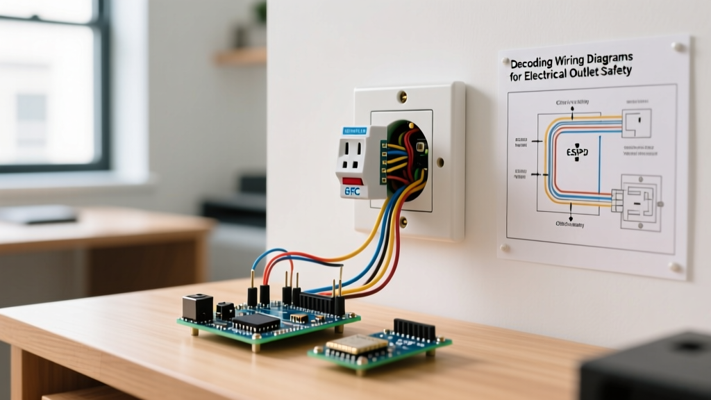

The Diagnostic Reality of Outlet Installation
When homeowners search for how do i install a new electrical outlet, most tutorials assume the existing wiring is flawless. In reality, legacy homes (pre-1980) and even newer builds often harbor hidden junction box faults, degraded backstab connections, or tripped upstream GFCIs. Swapping a receptacle without a diagnostic pre-check is the leading cause of "dead outlet" callbacks for professional electricians.
This guide merges the physical installation process with rigorous electrical troubleshooting. We will cover how to verify circuit integrity, identify multi-wire branch circuit (MWBC) hazards, and use precision diagnostic tools to ensure your new 15A or 20A Tamper-Resistant (TR) receptacle functions safely under the latest 2026 NEC standards.
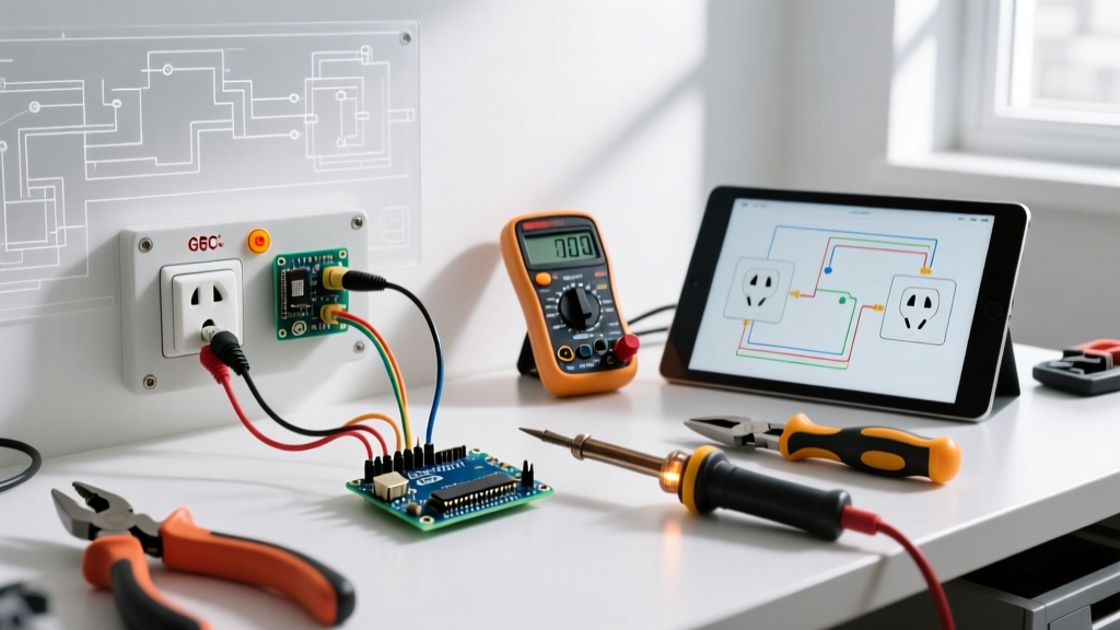
The Diagnostic Tool Loadout
Before stripping a single wire, you need the right diagnostic equipment. Skip the cheap neon testers; they cannot detect high-impedance faults or ghost voltages.
- Digital Multimeter (DMM): A True-RMS meter like the Fluke 117 ($180-$200) or Klein Tools MM400 ($45-$55) is mandatory for measuring exact voltage drops and verifying true open-neutrals.
- Non-Contact Voltage Tester (NCVT): The Klein Tools NCVT-3 ($30) detects both standard (12-1000V) and low-voltage (12-48V) signals, helping you trace switched loops.
- Receptacle Tester: The Gardner Bender GFI-3501 ($15) provides quick LED-based fault mapping for standard and GFCI circuits.
- Torque Screwdriver: NEC Article 110.14(D) requires terminations to be tightened to manufacturer specifications. A Wiha TorqueVario set to 14 in-lbs ensures secure connections without stripping brass screws.
Step 1: The Pre-Installation Diagnostic Sweep
Do not simply turn off the breaker and assume the box is dead. OSHA's Lockout/Tagout (LOTO) guidelines emphasize verifying the absence of voltage with a rated tester.
- Test Before Touch: Insert your NCVT into the existing outlet slots. Note which breaker controls it.
- Kill and Verify: Flip the breaker, lock the panel if possible, and re-test with the NCVT.
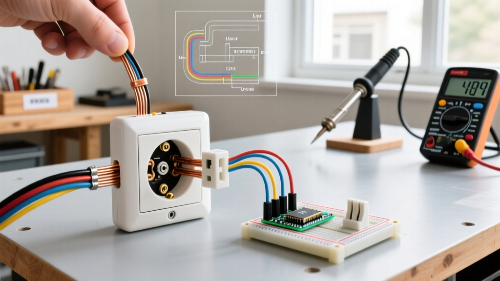
- The DMM Verification: NCVTs can be fooled by induced "ghost" voltages from adjacent live wires. Set your DMM to AC Voltage. Measure Hot-to-Neutral, Hot-to-Ground, and Neutral-to-Ground. All three must read 0.00V before you unscrew the faceplate.
Expert Insight: If your Neutral-to-Ground reads 1.0V to 3.0V with the circuit live before you shut it off, you have an undersized neutral wire or a loose connection upstream at the panel. Installing a new outlet won't fix this voltage drop; you must trace the branch circuit back to the breaker.
Step 2: Box Fill and Wire Gauge Diagnostics
Once the faceplate is off, diagnose the physical environment of the junction box. Overcrowded boxes cause heat buildup and arcing, a major fire hazard addressed in NFPA's National Electrical Code (NEC) Article 314.16.
Wire Gauge vs. Receptacle Rating Matrix
| Wire Gauge (AWG) | Breaker Size | Allowed Receptacle | Diagnostic Red Flag |
|---|---|---|---|
| 14 AWG (White/Copper) | 15 Amp | 15A Duplex TR | Using a 20A receptacle on 14 AWG wire (NEC Violation) |
| 12 AWG (Yellow/Copper) | 20 Amp | 15A or 20A Duplex TR | 12 AWG wire on a 15A breaker (Safe, but limits circuit capacity) |
| 10 AWG (Orange/Copper) | 30 Amp | N/A (Standard outlets) | Standard 15A/20A outlets cannot accept 10 AWG wire; requires pigtailing to 12 AWG |
Step 3: Termination and Inline Troubleshooting
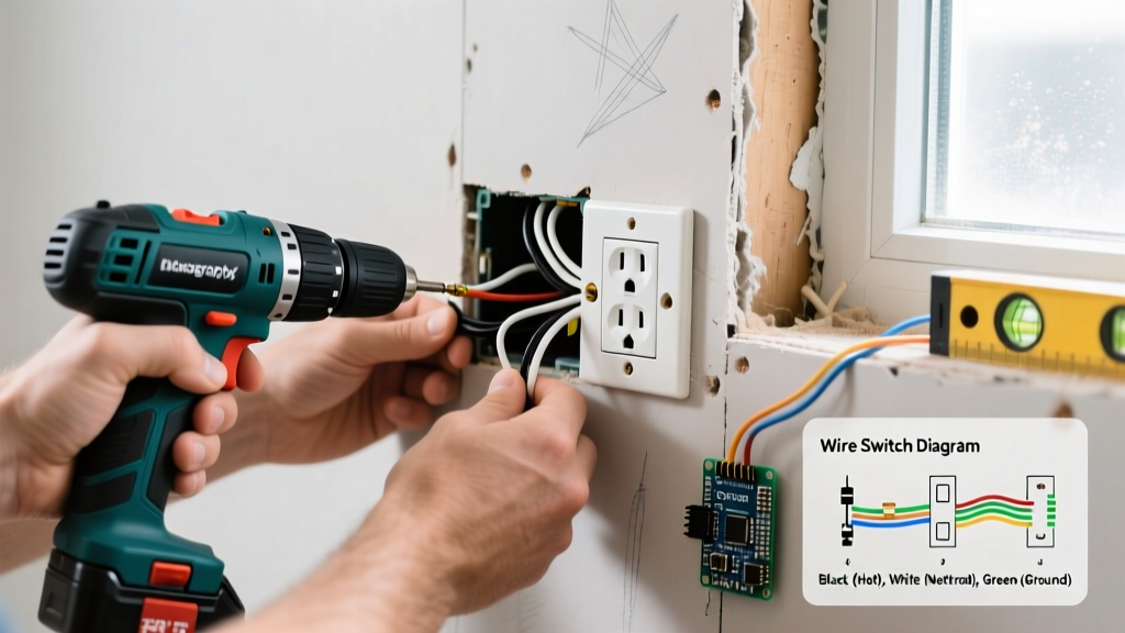
The physical installation is where most DIYers introduce new faults. The "how do I install" process must prioritize termination integrity over speed.
Never Use Push-In Backstabs
While modern push-in connectors (not the old friction backstabs) are UL-listed, professional electricians overwhelmingly prefer side-screw terminations or pressure plates. Friction backstabs in older outlets degrade due to thermal expansion and contraction, leading to high-resistance arcing.
- The Fix: Strip exactly 3/4 inch of insulation using wire strippers. Form a tight "J-hook" with the copper conductor.
- The Direction: Loop the wire clockwise around the brass (hot) and silver (neutral) screws. This ensures the screw pulls the wire tighter as it is torqued down.
- The Torque: Tighten to 14 in-lbs. If the wire insulation is pinched under the screw head, or if bare copper is exposed outside the terminal, redo it.
Step 4: Post-Installation Troubleshooting Matrix
After wiring the new Leviton or Eaton receptacle, restoring power, and plugging in your tester, you might encounter fault codes. Use this diagnostic matrix to identify the root cause.
| Tester LED Pattern | DMM Reading (Hot-Neutral) | Diagnosis | Corrective Diagnostic Action |
|---|---|---|---|
| Open Neutral | 120V (Ghost) / 0V under load | Neutral wire is disconnected upstream or at a wire nut in the box. | Remove receptacle. Check all white wire nuts. Tug-test pigtails. Trace to previous junction box. |
| Hot/Neutral Reversed | 120V (Polarity inverted) | Black wire on silver screw, white wire on brass screw. | Turn off breaker. Swap the hot and neutral wires on the side terminals. |
| Open Ground | 120V (Hot-Grd reads 0V) | No equipment grounding conductor (EGC) present, or bootleg ground. | Verify bare/green wire is bonded to the green screw and the metal box (if applicable). If no ground exists, NEC requires a GFCI receptacle labeled "No Equipment Ground". |
| Dead Outlet (No Lights) | 0.00V across all terminals | Tripped upstream GFCI, tripped breaker, or broken hot conductor. | Check bathrooms, garages, and kitchens for tripped GFCIs. Check panel for tripped AFCI/GFCI breakers. |
Advanced Diagnosis: The Multi-Wire Branch Circuit (MWBC) Trap
If you open a junction box and find two hot wires (one black, one red) sharing a single white neutral wire, you have an MWBC. This setup uses 240V across two 120V legs to balance the load.
The Danger: If you are replacing an outlet on an MWBC and you break the "tab" on the neutral (silver) side to split the top and bottom receptacles, you will place the full 240V load across the 120V appliances plugged into them, instantly destroying electronics and risking a fire. Furthermore, if you disconnect the shared neutral without turning off both breakers, the neutral wire will carry the unbalanced return current, potentially electrocuting you.
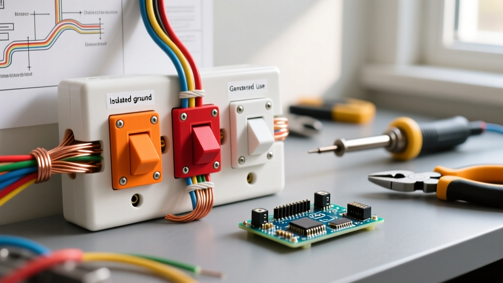
The Diagnostic Rule: Always pigtail MWBC neutrals. Never use the receptacle's internal brass/silver tabs as a pass-through for shared neutrals. Use a wire nut to join the incoming red, black, and white wires to short 6-inch pigtails that terminate directly onto a single receptacle.
GFCI and AFCI Compliance in 2026
When diagnosing why a new outlet trips immediately upon installation, consider the location. The U.S. Consumer Product Safety Commission (CPSC) and recent NEC updates mandate Ground-Fault Circuit Interrupter (GFCI) protection in all wet and damp locations, including kitchens, bathrooms, garages, and outdoor patios. Furthermore, Arc-Fault Circuit Interrupter (AFCI) protection is required in almost all living spaces (bedrooms, living rooms, hallways).
If your new standard duplex receptacle trips the breaker instantly, you likely have a ground fault upstream, or you have miswired the LINE vs. LOAD terminals on an upstream GFCI device. Always connect incoming power to the LINE terminals. Only connect downstream outlets you wish to protect to the LOAD terminals.
Summary Checklist for a Flawless Installation
- Verify absence of voltage with a True-RMS DMM, not just an NCVT.
- Confirm wire gauge matches the breaker amperage (14 AWG = 15A; 12 AWG = 20A).
- Inspect for MWBCs (red/black hots) and pigtail all shared neutrals.
- Terminate using side-screws with clockwise J-hooks, torqued to 14 in-lbs.
- Test with a receptacle analyzer to confirm correct polarity and ground continuity.
By treating the installation process as a diagnostic procedure, you eliminate the guesswork. You aren't just swapping plastic and brass; you are validating the safety and integrity of your home's electrical branch circuit.