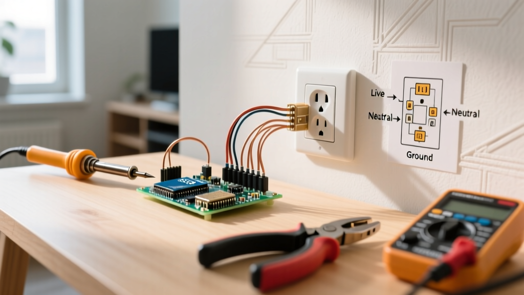

Why Standard Outlets Fail: Beyond the Breaker
When a 120V receptacle stops working, the immediate instinct is to check the breaker panel. However, the National Fire Protection Association (NFPA) notes that a significant percentage of residential electrical failures stem from degraded terminal connections, miswired downstream circuits, and improper grounding at the receptacle level. Understanding how to read and apply a standard wiring diagram for outlet configurations is the most critical skill for diagnosing these hidden faults.
In this guide, we move past basic 'plug-in-a-lamp' testing. We will use diagnostic matrices, multimeter measurements, and schematic analysis to identify complex failure modes, from bootleg grounds to Multi-Wire Branch Circuit (MWBC) neutral overloads.
Safety Warning: Always verify the circuit is de-energized using a non-contact voltage tester (NCVT) and a CAT III rated multimeter before removing any receptacle faceplate. Never assume a wire is dead based solely on a wall switch or breaker position.
Decoding the Standard 120V Wiring Diagram for Outlet Terminals
A standard NEMA 5-15R receptacle features three distinct connection points. When reviewing a wiring diagram for outlet troubleshooting, you must map the physical terminals to their electrical functions:
- Brass Terminals (HOT/LINE/LOAD): Connects to the black (or red) ungrounded conductor. This carries the 120V potential.
- Silver Terminals (NEUTRAL): Connects to the white grounded conductor. This completes the circuit back to the panel's neutral bus bar.
- Green Terminal (GROUND): Connects to the bare copper or green Equipment Grounding Conductor (EGC). This provides a low-impedance fault path to trip the breaker.
The 'Backstab' vs. 'Side-Wire' Connection Failure Mode
One of the most common reasons an outlet fails intermittently is the use of push-in 'backstab' connections. While the National Electrical Code (NEC) NFPA 70 permits them for 14 AWG solid wire, they are a primary culprit in thermal cycling failures. The internal brass wiper loses tension over years of heating and cooling, leading to high-resistance arcing.
Expert Tip: When replacing a faulty receptacle, use commercial-grade models like the Leviton T5262 (approx. $4.50 per unit in 2026). These feature deep side-wire saddle clamps that accept up to two 12 AWG wires. Torque the terminal screws to the manufacturer's specification—typically 14 in-lbs for Leviton devices—to prevent cold-flow loosening.
Diagnostic Matrix: Matching Symptoms to Wiring Faults
When your receptacle tester or multimeter indicates an anomaly, cross-reference the readings with this diagnostic matrix to pinpoint the exact error in the wiring diagram.
| Observed Symptom | Tester LED Pattern | Multimeter Reading | Wiring Diagram Fault |
|---|---|---|---|
| Dead Outlet | All LEDs Off | 0V (Hot to Neutral) | Open Hot (disconnected brass terminal or tripped upstream GFCI). |
| Shock from Appliance | Open Ground | 120V (Hot to Neu), 0V (Hot to Gnd) | Missing EGC at green terminal or broken ground wire in cable. |
| Lamp Flickers / Buzz | Correct (but loose) | Fluctuating 110V-125V | Backstab connection failure or loose wire nut at upstream junction. |
| Reversed Polarity | Hot/Neu Swapped | 120V on Silver Screw to Ground | Hot and Neutral wires reversed at terminal screws. |
| Downstream Dead (GFCI) | N/A (Standard Tester) | 120V on Line, 0V on Load | Load and Line wires swapped on GFCI diagram. |
Step-by-Step Troubleshooting Using Your Diagram
Step 1: Voltage Verification and Tool Selection
Do not rely on $10 neon testers. For accurate 2026 diagnostics, invest in a True-RMS multimeter like the Fluke 117 (retailing around $195) or the Klein Tools MM400 (approx. $55). Set the dial to AC Voltage (V~).
- Insert the black probe into the shorter (Hot) slot and the red probe into the longer (Neutral) slot. You should read 120V (±5%).
- Move the red probe to the U-shaped Ground slot. You should still read 120V.
- Measure between Neutral and Ground. This should read 0V to 2V. If it reads 120V, you have a severe bootleg ground or a swapped neutral/hot upstream.
Step 2: Identifying and Eliminating Bootleg Grounds
A 'bootleg ground' occurs when a previous DIYer or unlicensed handyman installs a jumper wire between the silver (neutral) terminal and the green (ground) terminal to trick a standard 3-prong receptacle tester into showing a 'Correct' reading. This is incredibly dangerous. If the neutral wire ever disconnects upstream, the metal casing of any plugged-in appliance becomes energized at 120V.
How to diagnose: Turn off the breaker, remove the receptacle from the box, and inspect the green terminal. If a jumper wire connects the silver and green screws, remove it immediately. The Consumer Product Safety Commission (CPSC) strictly warns against false grounding practices. If no true ground wire exists in the wall, you must replace the receptacle with a GFCI and label it 'No Equipment Ground' per NEC 406.4(D)(2).
Step 3: Resolving Load vs. Line Confusion
With the expanded AFCI and GFCI requirements in the 2026 NEC cycle, more outlets are protected by upstream GFCI/AFCI devices. If a standard outlet is dead, but the breaker is on, it is likely downstream of a GFCI. If you are replacing the GFCI itself, confusing the LINE (power from panel) and LOAD (power to downstream outlets) terminals on the wiring diagram will result in the GFCI working, but all downstream outlets remaining dead. Always use a non-contact voltage tester to identify the live feed wire before disconnecting the old device.
Advanced Edge Cases: Multi-Wire Branch Circuits (MWBC)
If you open a junction box or receptacle box and find a red wire, a black wire, and a white wire connected to a single 120V duplex receptacle, you are dealing with a Multi-Wire Branch Circuit. In this diagram, the black and red wires are on two separate 120V breakers that share a single neutral wire.
The Fatal Flaw: If the two breakers are not on opposite phases (Leg A and Leg B) and are not tied together with a handle tie (NEC 210.4), the shared neutral can carry up to 40 amps (20A + 20A) on a wire rated for only 20 amps, causing a hidden fire hazard inside the walls. Furthermore, if an electrician turns off only one breaker to work on the outlet, the other half of the receptacle remains live, posing a lethal shock risk.
Diagnostic Action: Use your multimeter to measure the voltage between the black and red wires. If it reads ~240V, they are on opposite legs (safe). If it reads 0V, they are on the same leg (dangerous neutral overload). Install a 2-pole breaker or an approved handle tie immediately.
When to Call a Licensed Electrician
While a wiring diagram for outlet troubleshooting empowers you to fix reversed polarity, swap out backstabbed connections, and identify open grounds, certain scenarios require a licensed professional:
- Melted or scorched terminal screws: Indicates a high-amperage fault or severe arcing that may have damaged the branch circuit wiring insulation.
- Aluminum wiring (1960s-1970s): Requires specialized CO/ALR rated receptacles and antioxidant paste (e.g., Noalox). Improper termination of aluminum wire leads to oxidation and house fires.
- Missing ground wires in older Knob & Tube or early Romex: Upgrading the entire circuit to include an EGC or installing whole-home GFCI protection requires panel-level work.
By systematically applying the wiring diagram to your physical multimeter readings, you transform outlet troubleshooting from a guessing game into a precise, safe, and code-compliant science.