
Mastering the Wiring Diagram for Adding Electrical Outlet
Adding electrical outlet circuits to an existing wall is one of the most common home improvement tasks, yet it remains a frequent source of DIY electrical fires when executed improperly. According to the Consumer Product Safety Commission (CPSC), faulty receptacle wiring and overloaded circuits contribute to tens of thousands of residential fires annually. As we navigate the 2026 housing landscape, where high-draw smart home devices and EV chargers are ubiquitous, understanding the precise wiring diagrams for adding an outlet is no longer optional—it is a critical safety requirement.
This comprehensive wiring diagram reference breaks down the three most common scenarios for adding electrical outlet receptacles: end-of-run extensions, middle-of-run daisy chains, and GFCI-protected drops. We will also cover the National Electrical Code (NEC) box fill calculations and torque specifications that separate amateur hacks from professional-grade installations.
Pre-Wiring Checklist: NEC Code & Box Fill Calculations
Before you cut a single hole in your drywall, you must verify that the existing circuit can handle the additional load and that your junction box meets the volumetric requirements of NEC Article 314. The National Fire Protection Association (NFPA) mandates strict box fill calculations to prevent wire insulation damage from overcrowding and heat buildup.
Wire Gauge and Breaker Sizing Matrix
| Wire Gauge (NM-B) | Breaker Size | Max Continuous Load (80% Rule) | NEC Box Fill Volume per Wire |
|---|---|---|---|
| 14 AWG | 15 Amp | 1,440 Watts | 2.0 Cubic Inches |
| 12 AWG | 20 Amp | 1,920 Watts | 2.25 Cubic Inches |
| 10 AWG | 30 Amp | 2,880 Watts | 2.5 Cubic Inches |
Real-World Box Fill Math (12 AWG Example)
Suppose you are adding an outlet in the middle of a run (daisy-chaining) using 12 AWG wire on a 20-amp circuit. Here is how you calculate the required box volume:
- Incoming wires: 1 Hot, 1 Neutral, 1 Ground
- Outgoing wires: 1 Hot, 1 Neutral, 1 Ground
- Device (Receptacle): Counts as 2 conductors
- Total Conductor Count: 6 current-carrying conductors + 1 ground (grounds count as 1 total, regardless of quantity) + 2 for the device = 8 volume allowances.
- Total Volume Required: 8 x 2.25 cubic inches = 18.0 cubic inches.
Pro Tip: A standard Carlon B114R single-gang old-work box only offers 14 cubic inches of space. For a middle-of-run 12 AWG installation, you must upgrade to a deep single-gang box (like the B120R at 20 cubic inches) or a 4-inch square metal box with a single-gang mud ring to remain NEC compliant.
Diagram 1: Adding Electrical Outlet at the End of a Run
This is the simplest wiring configuration, used when the new outlet will be the final device on the circuit branch. You are pulling a single 2-wire cable (Hot, Neutral, Ground) from the upstream source to the new box.
Step-by-Step Termination Guide
- Strip the Sheathing: Remove exactly 8 inches of the outer PVC jacket using a cable ripper. Do not use a utility knife, which can nick the inner insulation and create a micro-fracture that fails under thermal cycling.
- Strip the Conductors: Use the built-in strip gauge on the back of your receptacle. For standard Leviton or Eaton 15A/20A duplex receptacles, this is exactly 3/4 of an inch. Stripping too little leaves exposed copper outside the terminal; stripping too much exposes bare wire to accidental contact.
- Connect the Ground: Loop the bare copper wire clockwise around the green grounding screw. The clockwise loop ensures that tightening the screw pulls the loop tighter rather than pushing it out.
- Connect the Neutral: Attach the white wire to the silver terminal screw.
- Connect the Hot: Attach the black wire to the brass terminal screw.
Critical E-E-A-T Warning: The Push-In Backstab Debate
Many modern receptacles feature push-in (backstab) quick-connect holes on the back. While UL-listed, master electricians overwhelmingly avoid them for permanent installations. The internal spring-loaded brass grips lose tension over years of thermal expansion and contraction, leading to high-resistance arcing. Always use the side screw terminals or, if time is critical, use a side-wire clamp receptacle (like the Leviton T52-A) which mechanically traps the wire under a plate via the screw.
Diagram 2: Daisy-Chaining (Middle of a Run)
When adding electrical outlet receptacles between two existing devices, you must pass power through the new box. This requires two cables entering the box: one from the panel (line) and one to the next downstream device (load).
The Pigtailing Method vs. Terminal Jumping
Novices often connect the incoming and outgoing black wires to the two brass screws on the same side of the receptacle, doing the same for the white wires on the silver side. While technically functional, this makes the receptacle itself the bridge for the circuit. If the receptacle fails or is removed for replacement, the entire downstream circuit loses power.
The Professional Standard: Pigtailing
- Take a 6-inch piece of 12 AWG (or 14 AWG) wire matching your circuit color.
- Use a wire connector to join the incoming wire, the outgoing wire, and the 6-inch pigtail together. For 12 AWG, use an Ideal 34 Yellow or WAGO 221-413 lever nut.
- Connect the free end of the pigtail to the receptacle terminal screw.
- Repeat for the neutral and ground wires. (Note: NEC requires the ground wire to be pigtailed so the grounding path is never interrupted by the removal of the device).
Diagram 3: Adding a GFCI Outlet for Wet Locations
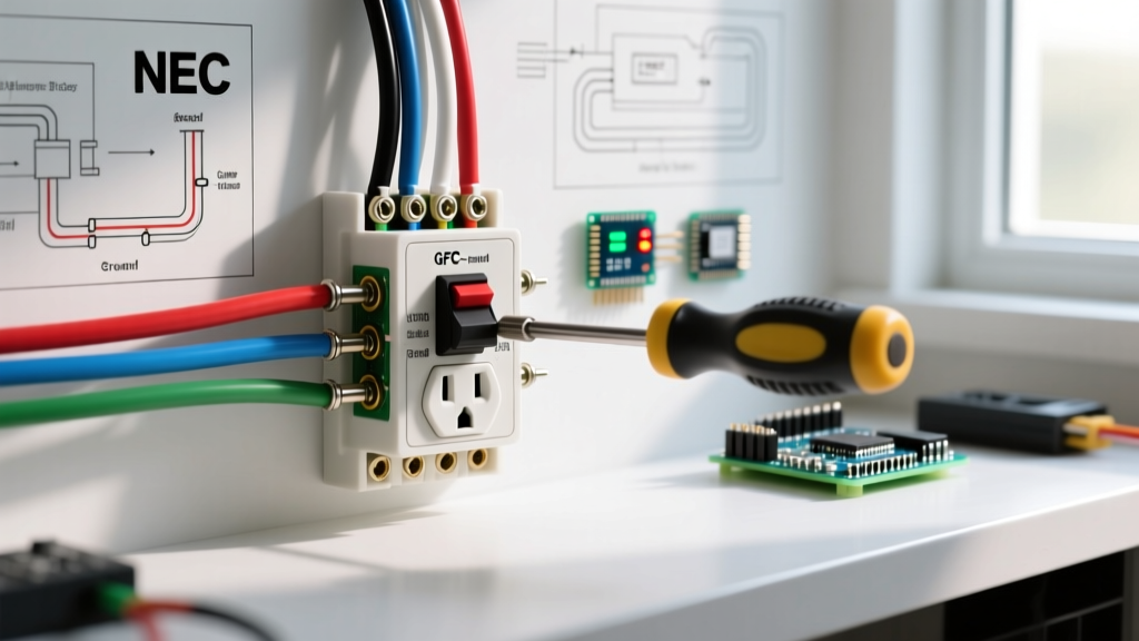
Under the latest NEC updates, GFCI (Ground Fault Circuit Interrupter) protection is mandatory for all 125-volt, 15- and 20-amp receptacles in kitchens, bathrooms, garages, outdoors, and unfinished basements. When adding electrical outlet drops in these zones, you must use a GFCI receptacle, such as the highly reliable Leviton GFNT2-W SmartlockPro.
Line vs. Load Terminal Mapping
GFCI receptacles have two distinct sets of terminals: LINE and LOAD. Wiring these backward will result in a receptacle that provides power but zero ground-fault protection, creating a lethal hazard.
| Terminal Set | Function | Wiring Connection |
|---|---|---|
| LINE | Receives power from the breaker panel. | Connect the incoming Hot (Black) and Neutral (White) from the source cable here. |
| LOAD | Sends GFCI-protected power downstream. | Connect the outgoing Hot and Neutral to downstream standard outlets here. Leave these empty if the GFCI is the end of the run. |
Testing Protocol: After installation, press the 'TEST' button on the GFCI face. The 'RESET' button should pop out, and power to the receptacle (and any downstream LOAD devices) must immediately cease. Use a Klein Tools RT250 GFCI tester to verify wiring integrity before energizing the circuit.
2026 Material Costs & Tool Requirements
Budgeting accurately for your wiring diagram project requires current market pricing. Here is a realistic breakdown for adding a single 20-amp outlet drop assuming you are pulling wire from an existing junction box 25 feet away:
- Southwire 12/2 SIMpull NM-B (50ft coil): ~$28.00
- Carlon B120R 20-cu-in Old Work Box: ~$3.50
- Leviton T52-A 20A Tamper-Resistant Receptacle: ~$2.80
- WAGO 221-413 Lever Nuts (10-pack): ~$5.50
- Total Material Cost: ~$39.80
The Torque Screwdriver Requirement
NEC 110.14(D) explicitly requires that terminations be tightened to the manufacturer's specified torque. Hand-tightening is no longer code-compliant for new installations. A standard 15A/20A receptacle typically requires 12 to 14 inch-pounds of torque. Investing in a Wiha 645P insulated torque screwdriver (approx. $65) ensures you meet this code requirement and prevents terminal loosening over time.
Troubleshooting Common Wiring Mistakes
Even with a perfect wiring diagram in hand, execution errors can cause immediate breaker trips or latent hazards. Use this diagnostic matrix if your new outlet fails to operate:
- Breaker Trips Immediately: You likely have a hot-to-ground short. Check for nicked insulation where the wire enters the metal box, or ensure a bare ground wire isn't touching the brass hot terminal screw inside a crowded junction box.
- Receptacle Has Power but GFCI Downstream Trips: You wired the LINE and LOAD terminals backward on the upstream GFCI device.
- Reversed Polarity (Hot/Neutral Swapped): A receptacle tester shows a red light on the right. You connected the black wire to the silver screw and the white wire to the brass screw. Swap them immediately; reversed polarity leaves the device socket energized even when an appliance switch is turned off.
- Open Ground: The ground wire was not properly secured to the green screw, or the grounding path back to the panel is broken. Do not use a 'cheater plug' or bootleg ground to bypass this; it defeats the safety mechanism of the entire circuit.
By strictly adhering to these wiring diagrams, respecting NEC box fill mathematics, and utilizing proper torque specifications, adding electrical outlet circuits becomes a safe, code-compliant upgrade that adds lasting value and functionality to your home's electrical infrastructure.