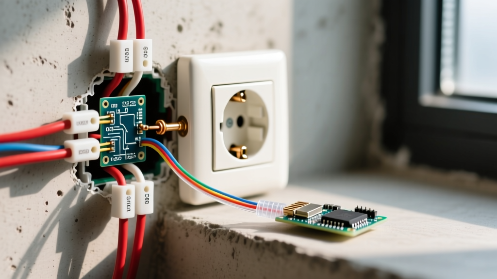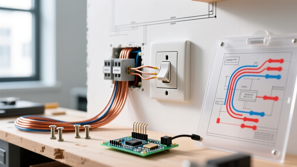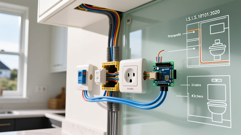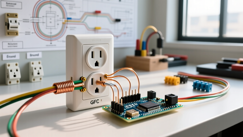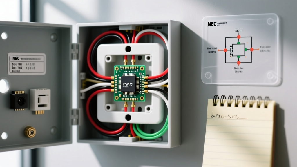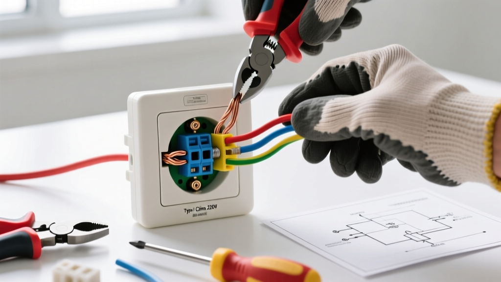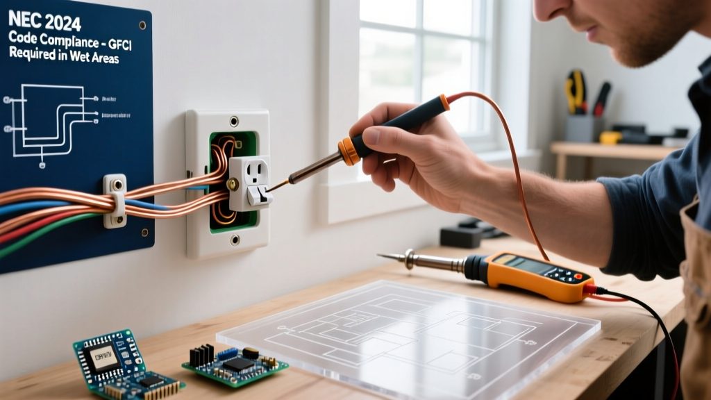

The Hidden Dangers of Non-Compliant Wiring
When adding an electrical outlet to an existing circuit, the physical act of connecting wires is only half the battle. The true challenge lies in navigating the National Electrical Code (NEC) to ensure the new receptacle does not introduce a fire hazard or shock risk. According to the U.S. Consumer Product Safety Commission (CPSC), electrical distribution and lighting equipment are involved in over 50,000 home fires annually, many stemming from overloaded circuits, improper box fill, or degraded connections.
This guide provides a deep-dive, expert-level framework for adding a receptacle safely, focusing on 2026 industry standards, precise load calculations, and strict NEC compliance. Whether you are extending a 15-amp lighting circuit or tapping into a 20-amp kitchen small-appliance branch circuit, the margin for error is zero.
Critical Safety Warning: Never assume a circuit is de-energized simply because a wall switch is off or a breaker appears tripped. Always verify the absence of voltage at the specific terminal screws using a Category III or IV non-contact voltage tester and a multimeter before touching any conductors.
Decoding NEC Mandates for New Receptacles
The National Fire Protection Association (NFPA) updates the NEC on a three-year cycle, and modern code enforcement is stricter than ever. When adding an electrical outlet, your installation must comply with the current adopted code in your jurisdiction (typically the 2023 or upcoming 2026 NEC). Here are the three non-negotiable mandates:
1. Tamper-Resistant (TR) Requirements
Under NEC Article 406.12, all 15-amp and 20-amp, 125-volt and 250-volt receptacles installed in dwelling units must be tamper-resistant. TR receptacles feature internal spring-loaded shutters that only open when equal pressure is applied to both slots simultaneously. Standard receptacles are strictly prohibited in living spaces, hallways, and kitchens. Expect to pay between $3.50 and $6.00 for a high-quality TR receptacle, such as the Leviton T5262 (15A) or Leviton T6262 (20A).
2. GFCI and AFCI Protection
Ground Fault Circuit Interrupter (GFCI) and Arc Fault Circuit Interrupter (AFCI) protections are location and circuit-dependent:
- GFCI (NEC 210.8): Mandatory for outlets in kitchens, bathrooms, garages, crawlspaces, unfinished basements, and outdoors. If you are adding an outlet in these zones, it must have GFCI protection, either via a GFCI receptacle or a GFCI breaker.
- AFCI (NEC 210.12): Required for almost all 120-volt, single-phase, 15- and 20-amp branch circuits supplying living rooms, bedrooms, hallways, and closets. If you extend an existing living room circuit, the entire circuit must be AFCI protected at the panel. Modern combination-type AFCI breakers (e.g., Square D QO120CAFI, approx. $55) detect both parallel and series arcing.
Box Fill Calculations: Avoiding the Overcrowding Hazard
One of the most frequently cited code violations when adding an electrical outlet is exceeding the maximum box fill capacity outlined in NEC Article 314.16. Cramming too many wires into a standard electrical box traps heat, degrading wire insulation and creating a severe fire risk.
To calculate box fill, you must determine the cubic inch (cu in) allowance for every item inside the box:
- 14 AWG Wire: 2.0 cu in per conductor
- 12 AWG Wire: 2.25 cu in per conductor
- Ground Wires: Count as a single allowance based on the largest ground wire present
- Internal Clamps: Count as a single allowance based on the largest wire
- Device (Receptacle/Switch): Counts as two allowances based on the largest wire connected to it
Real-World Calculation Example
Imagine you are adding a 15-amp outlet to an existing 14 AWG circuit. The box will contain: two 14 AWG hot wires (incoming and outgoing), two 14 AWG neutral wires, two 14 AWG ground wires, one device, and internal clamps.
- 4 current-carrying conductors (2 hots, 2 neutrals) x 2.0 = 8.0 cu in
- 1 ground allowance x 2.0 = 2.0 cu in
- 1 clamp allowance x 2.0 = 2.0 cu in
- 1 device allowance (counts as 2) x 2.0 = 4.0 cu in
- Total Required: 16.0 cubic inches.
A standard single-gang "old work" drywall box typically offers 14 to 18 cubic inches. You must check the stamp inside the box. If it is rated for 14 cu in, you must use a deeper 20 cu in or 22.5 cu in box to remain code-compliant.
Circuit Capacity and the 80% Continuous Load Rule
Before tapping into an existing circuit, you must verify the circuit has the ampacity to handle the new outlet's intended load. The NEC defines a continuous load as one expected to run for 3 hours or more. For continuous loads, you must derate the circuit capacity to 80%.
| Breaker Size | Wire Gauge (Copper) | Max Total Capacity (Watts @ 120V) | Continuous Load Limit (80%) | Receptacle NEMA Config |
|---|---|---|---|---|
| 15 Amp | 14 AWG (or 12 AWG) | 1,800W | 1,440W | 5-15R |
| 20 Amp | 12 AWG | 2,400W | 1,920W | 5-20R or 5-15R |
Note: You can install a 15-amp receptacle on a 20-amp circuit, provided there is more than one receptacle on the circuit (NEC 210.21(B)(3)). However, you can never install a 20-amp receptacle on a 15-amp circuit.
Step-by-Step Installation Workflow
Follow this precise sequence to ensure a safe, low-resistance connection when adding your outlet.
Tools Required
- Fluke T+PRO or Klein Tools NCVT-2 voltage tester
- Klein Tools 11055 wire strippers (for 10-18 AWG solid/stranded)
- WAGO 221 Series Lever-Nuts (UL listed, superior to standard twist-on wire nuts for solid-to-stranded or tight box spaces)
- Torx/Phillips terminal screwdrivers
Execution Steps
- Isolate and Verify: Turn off the breaker. Test the existing outlet's hot-to-neutral, hot-to-ground, and neutral-to-ground to confirm 0V.
- Prepare the Conductors: Strip exactly 3/4 inch of insulation from the solid copper wires. Do not nick the copper; scoring the metal creates a weak point that will snap when folded into the box.
- Pigtail the Connections: Never use the receptacle itself as a splice point for downstream devices. If the circuit continues past this outlet, use WAGO 221 lever nuts to connect the incoming hot, outgoing hot, and a 6-inch 12 or 14 AWG black pigtail. Repeat for the neutral (white) wires. This ensures that if the receptacle fails, downstream devices do not lose their neutral return path—a major shock hazard.
- Terminate at the Screws: Loop the pigtail clockwise around the brass (hot) and silver (neutral) terminal screws. Tighten to the manufacturer's torque specification (typically 14 in-lbs for standard 15A/20A devices). The insulation should just touch the screw head; no bare copper should be exposed outside the terminal.
- Grounding: Attach the bare/green ground wire to the green grounding screw. If using a metal box, you must also pigtail a ground wire to the box's internal grounding clip or 10-32 ground screw.
- Fold and Secure: Carefully fold the wires in a "Z" pattern, pushing the grounds to the back, neutrals in the middle, and hots near the front. Secure the device with the provided 6-32 mounting screws.
Common Failure Modes and Code Violations
According to the Electrical Safety Foundation International (ESFI), improper installations are a leading cause of residential electrical anomalies. Avoid these critical failure modes:
The "Backstabbing" Thermal Hazard
Many cheap receptacles feature push-in (backstab) terminals on the rear. While technically UL-listed, master electricians universally avoid them. These terminals rely on a small internal spring to grip the wire. Over years of thermal cycling (heating up under load and cooling down), the spring tension relaxes. This creates a high-resistance connection, leading to localized melting, arcing, and eventually, a fire. Always use the side terminal screws or screw-down clamp plates.
Reversed Polarity and Bootleg Grounds
Connecting the hot wire to the silver screw and the neutral to the brass screw results in reversed polarity. While the device might still power on, the internal fuse of a plugged-in appliance will no longer protect the device's internal circuitry from short circuits. Furthermore, never create a "bootleg ground" by jumpering the neutral terminal to the ground screw to trick a receptacle tester. This energizes the chassis of plugged-in appliances if the neutral fails, presenting a lethal shock hazard.
Frequently Asked Questions
Can I add an outlet to a lighting circuit?
Yes, but with caveats. NEC allows mixing lighting and receptacles on a 15-amp general lighting branch circuit. However, you cannot add a receptacle to a circuit dedicated solely to hardwired smoke alarms, bathroom exhaust fans, or specialized equipment circuits. Always verify the existing breaker size and wire gauge before tapping in.
Do I need a permit to add a single outlet?
In most municipalities, adding a single receptacle to an existing circuit does not require a permit, provided you are not extending the circuit into a new room or altering the service panel. However, if you are running a new home run from the panel or adding outlets in a finished basement conversion, an electrical permit and subsequent inspection are legally required to ensure compliance with the National Electrical Code.
What if the existing wires are aluminum?
If you are tapping into older 1970s aluminum branch wiring (12 AWG AL), you cannot simply connect it to a standard copper pigtail using a wire nut. You must use CO/ALR rated receptacles or connect the wires using specialized Alumiconn lug connectors to prevent galvanic corrosion and thermal expansion mismatches, which are notorious for causing fires at the termination point.