
Decoding the Electrical Plug Wiring Diagram: Beyond the Basics
Wiring a replacement plug or assembling a custom extension cord seems straightforward until you factor in the National Electrical Code (NEC). A standard electrical plug wiring diagram does more than just show you which colored wire goes to which screw; it represents a critical safety architecture designed to prevent fires, shocks, and equipment damage. As we navigate the 2023 NEC cycle (the active standard for most jurisdictions entering 2026), understanding the code requirements behind the diagram is just as important as the physical connection.
This guide breaks down the exact pinouts, NEC code mandates, and professional wiring techniques for standard 120V (NEMA 5-15P and 5-20P) and 240V (NEMA 6-15P and L14-30P) plugs. We will reference industry-standard hardware, such as the Leviton 5266-C (15A residential plug) and the Hubbell 5362 (20A industrial plug), to provide actionable, code-compliant instructions.
Standard 120V NEMA Pinouts and Terminal Mapping
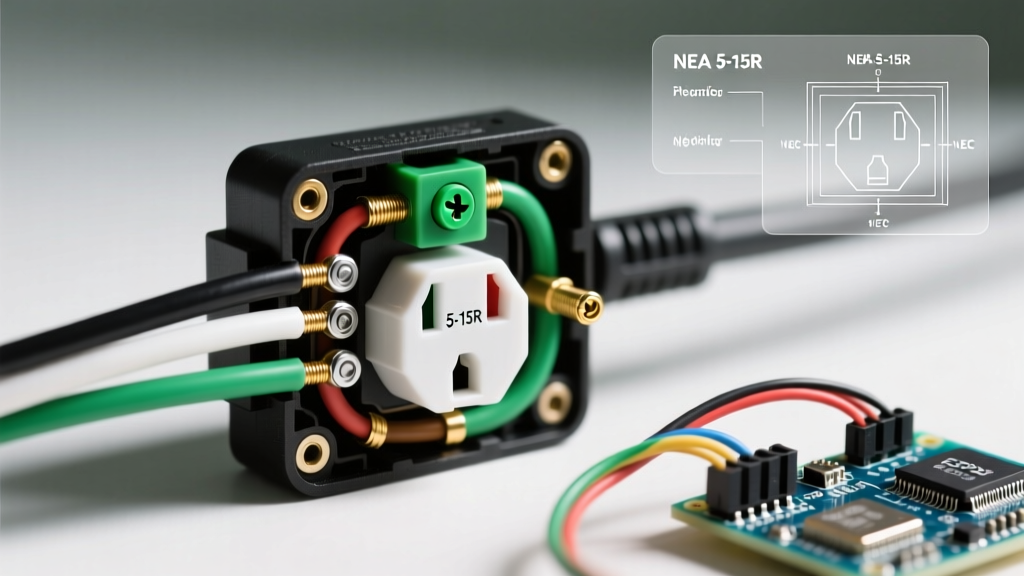
The most common electrical plug wiring diagram you will encounter is the NEMA 5-15P (15 Amp, 125V) and the NEMA 5-20P (20 Amp, 125V). The physical difference lies in the neutral blade: the 20A plug features a T-shaped neutral blade to accept both 15A and 20A receptacles. However, the internal terminal mapping remains consistent across both configurations.
| Terminal Screw Color | Wire Insulation Color | Function | Blade Shape / Position | NEC Reference |
|---|---|---|---|---|
| Brass (Gold) | Black (or Red/Blue) | Hot (Line) | Narrow vertical blade | NEC 200.2 (Polarity) |
| Silver | White (or Gray) | Neutral (Grounded) | Wide vertical blade (or T-slot on 20A) | NEC 200.2 (Continuity) |
| Green | Green (or Bare Copper) | Equipment Ground | U-shaped round pin | NEC 250.118 (Grounding) |
Expert Insight: Never rely solely on wire color if you are salvaging or reusing older flexible cords. Always use a multimeter to verify continuity from the plug blades to the wire ends before energizing, as foreign-manufactured cords sometimes use non-standard color coding (e.g., brown for hot, blue for neutral) which violates NEC Article 200.2 for domestic installations.
NEC Code Requirements Governing Plug Wiring
Simply connecting the wires to the correct terminals does not guarantee a code-compliant assembly. The National Fire Protection Association (NFPA) outlines strict mechanical and electrical requirements in the NEC and through OSHA enforcement for flexible cords and attachment plugs.
1. Strain Relief and Cord Grips (NEC Article 400.13)
Every attachment plug must feature an integral strain relief mechanism (cord grip). According to NEC 400.13, a flexible cord must be protected from damage, and the cord grip must securely clamp the outer jacket of the cable, not just the individual insulated conductors.
- The 1/4-Inch Rule: When stripping the outer jacket, leave at least 1/4 inch of the jacket inside the cord grip area. If the grip clamps only on the inner wire insulation, the cord can easily be pulled out of the terminals under tension, creating an immediate arc-flash or shock hazard.
2. Polarity and Grounding Continuity (NEC 250.4 & 406.4)
The NEC mandates that the grounding path must be permanent and continuous. When wiring a NEMA 5-15P plug, the green grounding screw must be connected to the equipment grounding conductor. Furthermore, OSHA flexible cord regulations strictly prohibit using the neutral wire as a ground, or bypassing the ground pin entirely to fit a 2-prong receptacle. Doing so voids the UL listing of the plug and violates federal workplace safety codes.
3. Conductor Length and the 'Break-Last' Ground Rule
A frequent failure mode in DIY plug wiring is cutting all three internal wires to the exact same length. Professional electricians follow a critical safety protocol: the grounding conductor should be stripped and routed slightly longer than the hot and neutral conductors. If the strain relief fails and the cord is violently yanked, the hot and neutral wires will pull out of their terminals first, de-energizing the circuit before the ground connection is severed. This ensures the equipment chassis never becomes energized while floating without a ground path.
240V and Twist-Lock Plug Wiring Diagrams
For heavy-duty applications like welders, air compressors, and portable generators, the standard electrical plug wiring diagram shifts to 240V configurations. These require strict adherence to phase and neutral mapping.
NEMA 6-15P and 6-20P (240V, No Neutral)
Used for baseboard heaters and small welders, these plugs feature two hot blades and a ground pin.
- Hot 1 (Brass): Black wire (120V Leg 1)
- Hot 2 (Brass): Red or White wire (120V Leg 2)
- Ground (Green): Bare or Green wire
NEMA L14-30P (125/250V, 30A Twist-Lock)
The standard for portable generators (e.g., using a Pass & Seymour L1430P plug), this 4-wire diagram is where most mistakes happen. The four terminals are clearly marked on the plug body:
- X (Hot 1): Black wire
- Y (Hot 2): Red wire
- W (Neutral): White wire (Connected to the Silver terminal)
- G (Ground): Green/Bare wire (Connected to the Green terminal)
Step-by-Step: Wiring a 15A Plug to Code
Follow this exact procedure to wire a standard Leviton 5266-C or equivalent 15A plug using a 14 AWG or 12 AWG SOOW/SJOOW flexible cord.
- Jacket Stripping: Use a cable ripper to slit the outer jacket exactly 1.5 inches from the end. Carefully remove the jacket without nicking the inner wire insulation. (Nicking the insulation violates UL electrical safety standards for flexible cords).
- Insulation Stripping: Strip exactly 5/8 inch of insulation from the three inner conductors. Do not twist the copper strands tightly; a gentle twist to keep them cohesive is sufficient. Over-twisting can cause the strands to splay under the terminal screw, reducing contact area and increasing resistance.
- Forming the Hook: Using needle-nose pliers, form a smooth, clockwise U-shaped hook at the end of each stripped wire. The clockwise direction is mandatory: as you tighten the screw (righty-tighty), the screw head will pull the wire loop tighter around the terminal post. A counter-clockwise loop will push the wire out from under the screw.
- Terminal Connection: Seat the black wire on the brass screw, white on the silver, and green on the green. Ensure no bare copper is exposed outside the terminal cup (which risks shorting to the plug casing), and ensure no insulation is trapped under the screw washer (which causes high-resistance heating).
- Torque and Clamp: Tighten the terminal screws firmly (typically 12 to 14 inch-pounds for standard residential plugs). Route the wires neatly so they do not cross or pinch against the internal cord grip. Assemble the plug housing and tighten the central strain-relief screw until the outer jacket is firmly immobilized.
Common Code Violations and Failure Modes
When inspecting electrical plug wiring diagrams in the field, safety inspectors frequently flag the following violations:
- The 'Push-In' Backwire Violation: While some receptacles allow push-in backwiring, NEC and UL standards heavily restrict or prohibit push-in connections on attachment plugs subject to vibration or movement. Always use screw-terminal or screw-clamp backwiring.
- Undersized Cord Gauge: Wiring a 20A plug (NEMA 5-20P) onto a 16 AWG lamp cord. The plug rating must never exceed the ampacity of the flexible cord. A 16 AWG cord is rated for 13A (per NEC Table 400.5) and must only be fitted with a 15A plug maximum, and practically should be limited to 10A for continuous duty.
- Missing Strain Relief Bushings: Using a replacement plug that lacks an internal cord grip, or removing the grip to fit a thicker cable. If the cable is too thick for the standard grip, you must use a larger plug body (like a Hubbell industrial series) designed for that specific cable OD (Outside Diameter).
Frequently Asked Questions (FAQ)
Can I wire a 3-prong plug to a 2-wire cord without a ground?
No. NEC Article 250.138 explicitly prohibits connecting an equipment grounding terminal to a circuit that lacks an equipment grounding conductor. If you only have a 2-wire (hot and neutral) cord, you must use a 2-prong NEMA 1-15P plug, provided the attached equipment is double-insulated (Class II) and does not require a ground.
Why did my GFCI trip when I plugged in my newly wired extension cord?
If a GFCI trips immediately upon plugging in a newly wired cord (even with no load attached), you likely have a 'bootleg ground' or a neutral-to-ground short inside the plug. Verify your electrical plug wiring diagram to ensure the white (neutral) and green (ground) wires are not touching, and that no stray copper strands are bridging the silver and green terminals.
Is it code-compliant to use a 15A plug on a 12 AWG cord?
Yes. You can always use a smaller overcurrent protection device (or plug rating) than the wire's maximum ampacity. A 12 AWG cord is rated for 20A, but fitting it with a 15A plug is perfectly legal and safe, provided the physical cord grip of the 15A plug can adequately clamp the thicker 12 AWG jacket without damaging it.