
The Anatomy of a Thermal Runaway
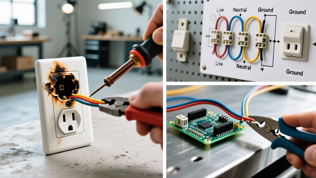
Discovering a burnt electrical outlet and plug is a glaring red flag indicating severe thermal runaway within your home's wiring system. According to the National Fire Protection Association (NFPA), electrical distribution and lighting equipment are responsible for tens of thousands of residential fires annually. A charred receptacle or melted plug prong is rarely an isolated cosmetic issue; it is the physical manifestation of high-resistance connections, overloaded circuits, or degraded metallurgy generating excessive ohmic heat ($P = I^2R$).
As of 2026, the National Electrical Code (NEC) has strictly tightened regulations surrounding termination torque and tamper-resistant requirements to mitigate these exact hazards. This comprehensive guide will walk you through the forensic diagnosis, safe extraction, and precise step-by-step installation required to replace a burnt electrical outlet and plug, ensuring your circuit is restored to modern safety standards.
Diagnostic Matrix: Why Did It Burn?
Before installing a replacement, you must identify the root cause of the failure. Installing a new receptacle on a compromised circuit will only result in a repeat failure. Review the diagnostic matrix below to identify your specific failure mode.
| Failure Mode | Visual Symptom | Root Cause & Physics |
|---|---|---|
| Backstabbed Connections | Melting localized to the rear plastic housing | Spring-loaded push-in contacts lose tension over years of thermal cycling, creating high resistance and micro-arcing. |
| Loose Terminal Screws | Charring isolated to one brass or silver screw | Vibration and improper initial torque reduce the wire-to-metal contact area, causing localized resistive heating. |
| Circuit Overload | Uniform scorch marks across both slots and the plug face | Drawing continuous loads near 15A/20A limits on degraded contacts, or using a 15A device on a 20A circuit without proper wire gauging. |
| Aluminum Wiring Oxidation | Grey/white powdery residue, severe pitting on wire | Aluminum oxide is highly resistive. Standard copper-rated devices will overheat rapidly without CO/ALR rating or antioxidant paste. |
Required Tools and Materials (2026 Standards)
Do not attempt this repair with basic household tools. Modern NEC compliance requires precision termination. Gather the following:
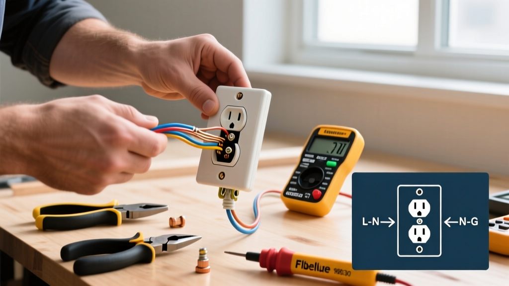
- Voltage Tester: Fluke 1AC-II VoltAlert Non-Contact Voltage Tester (Approx. $40)
- Wire Strippers: Klein Tools 11055 (10-20 AWG) for precise jacket removal without nicking copper.
- Torque Screwdriver: CDI 101MFRMH or similar, calibrated to 14 in-lbs.
- Receptacle: Leviton T5262-W 15A Tamper-Resistant (TR) Duplex Receptacle (Approx. $4.50). Note: NEC 406.12 mandates TR receptacles in all dwelling unit 125V/250V locations.
- Replacement Plug: Hubbell 5266C 15A Heavy-Duty Plug (Approx. $8.00).
- Wire Nuts/Connectors: Ideal Twister 341 Purple wire nuts (if pigtailing is required due to wire damage).
Step-by-Step Replacement Guide
Step 1: Isolate and Verify Power
Navigate to your main service panel and switch off the breaker controlling the affected room. Do not rely on wall switches or smart home software to isolate the circuit. Insert the Fluke VoltAlert into the top and bottom slots of the burnt outlet. The tool must remain completely dark and silent. For absolute certainty, remove the faceplate and test the side terminal screws directly. The U.S. Fire Administration (USFA) emphasizes that verifying dead circuits is the single most critical step in preventing arc flash injuries.
Step 2: Excavate and Inspect the Damage
Unscrew the center mounting screw and gently pull the burnt receptacle from the gang box. Inspect the Romex (NM-B) cable sheathing entering the box.
- Minor Damage: If the PVC jacket is merely discolored but intact, and the copper wire inside is bright and shiny, you can proceed.
- Severe Damage: If the PVC insulation is melted, brittle, or pulled back more than 1/2 inch, the wire is compromised. You must use flush cutters to remove the damaged copper until you reach clean, unoxidized metal. If this leaves you with less than 6 inches of slack inside the box, you must pigtail a new piece of 14 AWG (or 12 AWG) THHN copper wire using a listed connector.
Step 3: Precision Wire Preparation
Using your Klein wire strippers, remove exactly 3/4 inch of insulation from the black (hot), white (neutral), and bare (ground) wires. Do not strip more than necessary; exposed copper outside the terminal pad is a shock and short-circuit hazard. Ensure no deep nicks are present on the copper conductor, as nicks create structural weak points that snap under torque.
Step 4: Terminate with Calibrated Torque
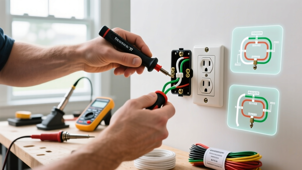
Form a tight 'J-hook' in the stripped wire using needle-nose pliers. Hook the wire around the brass (hot) and silver (neutral) terminal screws in a clockwise direction. This ensures that tightening the screw pulls the wire loop tighter rather than pushing it out.
NEC 110.14(D) Compliance: The National Electrical Code strictly requires that terminations be torqued to the manufacturer's specified values using a calibrated tool. For the Leviton T5262-W, set your torque screwdriver to exactly 14 in-lbs. Click the screw until the tool slips. This eliminates the primary cause of future thermal runaway: loose connections.
Secure the bare ground wire to the green grounding screw at the bottom of the yoke, also torqued to 14 in-lbs. Never use the backstab push-in holes on the rear of the receptacle, even if they are technically listed for use. Side-wiring with screw terminals provides vastly superior surface area contact and long-term thermal stability.
Step 5: Replacing the Burnt Appliance Plug
If the male plug on the appliance cord is also burnt, it must be replaced. A burnt plug indicates internal arcing within the molded plastic.
- Cut off the old molded plug using heavy-duty side cutters.
- Score the outer cord jacket about 1.5 inches from the cut end and peel it back to expose the three inner conductors.
- Strip 1/2 inch of insulation from the black, white, and green wires.
- Open the Hubbell 5266C replacement plug. Loosen the terminal screws and the cord grip clamp.
- Feed the cord through the plug housing first (a common mistake is forgetting this step).
- Loop the green wire clockwise around the green ground screw, the white wire around the silver screw, and the black wire around the brass screw. Tighten securely.
- Pull the cord back so the outer jacket sits inside the cord grip clamp, then tighten the clamp screws to provide vital strain relief.
Advanced Prevention: AFCI Protection and Thermal Imaging
Replacing the hardware fixes the immediate symptom, but upgrading the circuit protection prevents catastrophic failures. If your home was built before 2014, your bedroom and living room outlets may lack Arc Fault Circuit Interrupter (AFCI) protection. Upgrading the breaker in your panel to an Eaton BR115AFC (Approx. $45) will allow the panel to detect the high-frequency signatures of series and parallel arcing—often shutting off the circuit weeks before a receptacle physically melts.
Furthermore, the Consumer Product Safety Commission (CPSC) recommends periodic electrical inspections. For DIYers and professionals alike, using a handheld thermal imaging camera (like the FLIR C5) to scan outlets while under heavy load (e.g., running a space heater) can reveal hidden hot spots exceeding 120°F before they result in visible charring.
When to Call a Licensed Electrician
While this guide covers standard copper-wired 15A circuits, you must abort the DIY process and hire a licensed electrician if you encounter:
- Aluminum Branch Wiring: Identified by a silver/grey wire color or 'AL' stamping on the jacket. This requires specialized COPALUM crimping or specific AlumiConn lugs.
- Melted Sheathing Deep in the Wall: If the Romex jacket is melted beyond the drywall opening, the wire inside the wall cavity is a fire hazard and must be pulled and replaced.
- Federal Pacific or Zinsco Panels: If your breaker panel is one of these known defective brands, it may have failed to trip during the overload event that burnt your outlet. The entire panel requires immediate replacement.
Final Testing and Restoration
Once the Leviton receptacle is pushed back into the gang box and secured with the 6-32 mounting screws, install a new, clean faceplate. Do not reuse a faceplate that has been warped by heat. Restore power at the breaker panel. Use a 3-prong receptacle tester (like the Gardner Bender GRT-501) to verify correct wiring. The tester should display two amber lights, indicating correct hot/neutral/ground orientation. Finally, plug in the appliance with the newly installed Hubbell plug and monitor the faceplate temperature with your hand for the first 15 minutes of operation. It should remain completely cool to the touch.