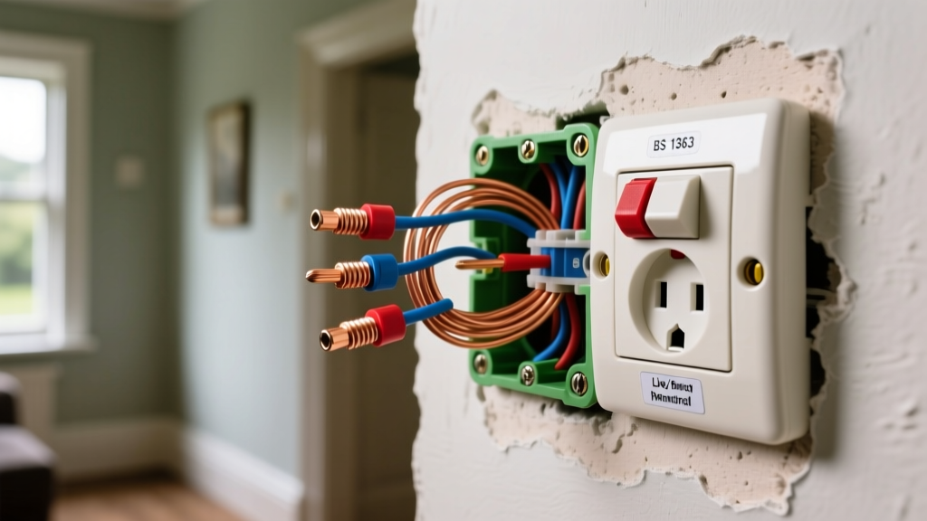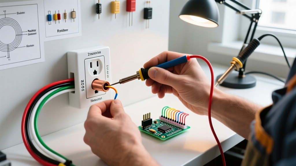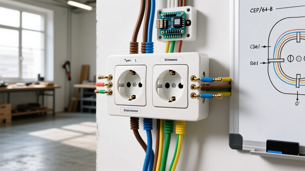

Introduction to the Duplex Electrical Outlet
The duplex electrical outlet is the backbone of modern residential power distribution. Technically classified as a NEMA 5-15R (15-amp) or NEMA 5-20R (20-amp) receptacle, it provides two distinct connection points for standard 120-volt appliances. While replacing or installing a duplex electrical outlet is a foundational DIY electrical task, it requires strict adherence to safety protocols and National Electrical Code (NEC) standards. A poorly terminated outlet can lead to high-resistance connections, thermal runaway, and electrical fires.
This beginner installation tutorial strips away the guesswork. We will cover exact tool requirements, precise wire stripping measurements, terminal torque specifications, and critical code mandates for 2026 residential wiring.
NEC Code Requirements and Safety Mandates
Before touching a single wire, you must understand the current regulatory landscape. According to the National Fire Protection Association (NFPA), which publishes the NEC, all 15A and 20A receptacles installed in dwelling units must be Tamper-Resistant (TR). TR receptacles feature internal spring-loaded shutters that prevent foreign objects from being inserted into a single slot, drastically reducing childhood shock hazards.
Furthermore, the U.S. Consumer Product Safety Commission (CPSC) heavily endorses TR receptacles as a permanent safety upgrade over removable plastic outlet caps. When purchasing your duplex electrical outlet, ensure the faceplate reads 'TR' and that the device is UL-listed or ETL-listed. Additionally, depending on the room (kitchens, bathrooms, garages, outdoors, or within 6 feet of a sink), Ground Fault Circuit Interrupter (GFCI) or Arc Fault Circuit Interrupter (AFCI) protection is strictly mandated by the latest NEC cycles.
Essential Tools and Materials
Professional results require professional-grade tools. Do not rely on dull utility knives or cheap testers. Budget approximately $45 to $80 for the required hand tools if you do not already own them.
- Receptacle: Leviton 5262-SW (15A TR Duplex, approx. $1.80) or Leviton 5362-W (20A TR Duplex, approx. $2.50).
- Voltage Tester: Fluke 1AC-II VoltAlert or Klein Tools NCVT-2 (Dual-Range). Cost: $25-$35.
- Wire Strippers: Klein Tools 11055 (10-20 AWG Solid). Cost: $28.
- Torque Screwdriver: Wiha 60601 or Klein Tools 32500 series with torque adapter. Cost: $40-$60.
- Screwdrivers: #2 Phillips and 3/16-inch flathead (insulated preferred).
- Needle-Nose Pliers: For forming wire hooks.
Step-by-Step Installation Guide
Follow these steps meticulously. The Occupational Safety and Health Administration (OSHA) emphasizes that verifying the absence of voltage is the most critical step in preventing fatal arc flashes and shocks.
Step 1: Kill the Power and Verify
Locate your main electrical panel and switch off the breaker controlling the circuit. Place a piece of tape over the breaker to prevent accidental re-engagement. Insert your non-contact voltage tester into the top and bottom slots of the existing outlet. The tester must remain completely silent and unlit. Next, remove the faceplate and unscrew the outlet from the gang box. Test the bare copper ground wire and the black (hot) wires directly to guarantee zero voltage.
Step 2: Prepare the Conductors
If you are working with existing wiring, inspect the copper for deep nicks or corrosion. If damaged, snip the ends back to clean copper. Using your Klein Tools 11055 wire strippers, strip exactly 3/4 inch of insulation from the black (hot), white (neutral), and bare/green (ground) wires. Do not strip more than 3/4 inch; exposed copper outside the terminal head is a severe shock and short-circuit hazard.
Step 3: Form the Terminal Hooks
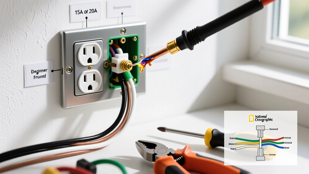
Using your needle-nose pliers, bend the stripped end of each wire into a tight 'J' hook. The hook must be shaped so that it wraps around the terminal screw in a clockwise direction. When you tighten the screw clockwise, the hook will pull tighter around the shaft. If hooked counter-clockwise, the screw will push the wire out from under the terminal head, leading to a high-resistance fault.
Step 4: Terminate and Torque
Connect the wires to the correct terminals on the duplex electrical outlet:
- Ground: Bare or green wire to the green terminal screw (usually at the bottom).
- Neutral: White wire to the silver-colored terminal screw.
- Hot: Black wire to the brass-colored terminal screw.
Once the hooks are seated under the screws, use your torque screwdriver. Leviton specifies a tightening torque of 12 to 14 inch-pounds for standard 15A and 20A terminal screws. Proper torquing prevents 'cold flow' (where the copper compresses over time and loosens the connection), which is a leading cause of residential electrical fires.
Step 5: Mount and Test
Carefully fold the wires into the back of the gang box using a 'Z' or accordion fold. Do not simply shove them in, as this can pinch the neutral wire against the hot terminal. Mount the outlet using the provided 6-32 mounting screws, ensuring the strap sits flush against the drywall or plaster ring. Restore power at the panel and test with a standard 3-prong outlet tester to confirm correct wiring (two amber lights indicate 'Correct').
Understanding Split-Wired (Half-Hot) Duplex Outlets
In many living rooms and bedrooms, you will encounter a split-wired duplex electrical outlet. This configuration allows the top receptacle to be controlled by a wall switch (for a lamp), while the bottom receptacle remains constantly hot. This is achieved by breaking the small brass connecting fin on the side of the outlet.
Pro Tip: Never break the silver fin (neutral side) unless you are working with a specific multi-wire branch circuit (MWBC) setup that requires a dedicated neutral return for each hot leg. Breaking the silver fin on a standard single-pole switch loop will cause a dead short or an open neutral hazard.
To break the hot fin, grip it with your needle-nose pliers and bend it back and forth until it snaps cleanly. You will then connect your constant hot wire to one brass screw and your switched hot wire to the other brass screw.
Comparison Matrix: 15A vs 20A Duplex Receptacles
Choosing the correct amperage rating for your duplex electrical outlet is dictated by the wire gauge and breaker size in your electrical panel. Never install a 20A receptacle on a 15A circuit, and never install a 15A receptacle on a 20A circuit (unless it is a multi-receptacle circuit, per NEC 210.21(B)(3)).
| Feature | 15-Amp Duplex (NEMA 5-15R) | 20-Amp Duplex (NEMA 5-20R) |
|---|---|---|
| Breaker Size | 15 Amp | 20 Amp |
| Wire Gauge Required | 14 AWG (or 12 AWG) | 12 AWG (or 10 AWG) |
| Physical Slot Design | Two parallel vertical slots | One vertical, one T-shaped (horizontal) slot |
| Max Continuous Load | 12 Amps (1440 Watts) | 16 Amps (1920 Watts) |
| Common Applications | Bedrooms, Living Rooms, Hallways | Kitchens, Bathrooms, Garages, Workshops |
| Average Retail Cost | $1.50 - $2.25 | $2.50 - $4.00 |
Critical Beginner Mistakes to Avoid
1. Using 'Backstab' Push-In Terminals
Many modern duplex outlets feature small holes on the back for pushing stripped wires directly into the device. While UL-listed and technically legal, professional electricians universally avoid these 'backstab' connections. The internal spring-metal grips have a tiny surface area. Over years of thermal expansion and contraction from appliance loads, these connections loosen, arc, and melt the plastic housing. Always use the side-wiring terminal screws or the screw-clamp plates found on higher-grade 'Spec-Grade' outlets.
2. Reversed Polarity
Connecting the black hot wire to the silver screw and the white neutral wire to the brass screw results in reversed polarity. While the appliance will still operate, the internal fuse or switch of the appliance will now interrupt the neutral path instead of the hot path. This means the internal components of the plugged-in device remain energized at 120V even when turned off, presenting a severe shock hazard if a user attempts to repair or clean the appliance.
3. Overfilling the Gang Box
The NEC mandates strict box-fill calculations based on the number of wires, clamps, and devices in a gang box. If you are adding new wires or pigtailing multiple cables in a standard 18-cubic-inch plastic box, you risk violating box-fill limits. Overcrowded boxes trap heat and make it nearly impossible to seat the duplex electrical outlet flush without crushing the conductors against the drywall edges.
Final Inspection Checklist
Before considering the job complete, run through this final verification sequence:
- Is the outlet completely flush with the wall, without the strap bending?
- Are all three terminal screws torqued to 12-14 in-lbs?
- Is the ground wire securely terminated to the green screw and the metal box (if applicable)?
- Does a 3-prong receptacle tester confirm correct wiring and proper grounding?
- Is the TR shutter mechanism functioning freely when a plug is inserted?
By following these precise specifications and respecting the physical limitations of the materials, your duplex electrical outlet installation will be safe, code-compliant, and built to last for decades.