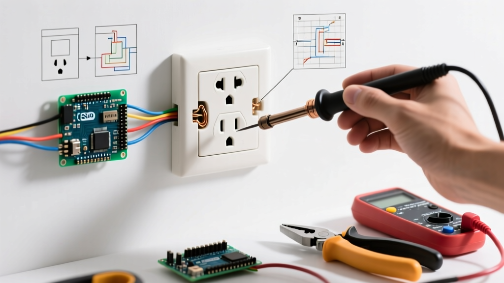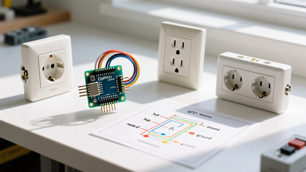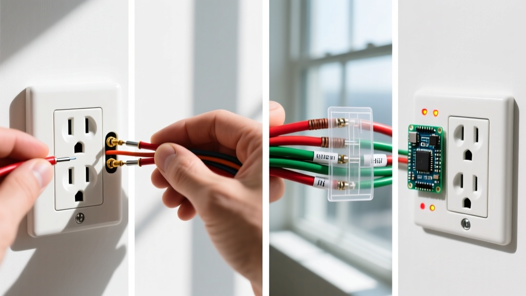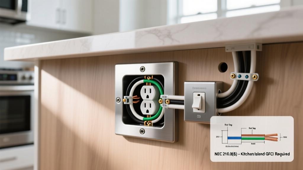

Decoding the Terminology: 3-Way vs. 2-Way Switches
Before diving into the inspection process, we must clarify a persistent point of confusion in residential electrical work. When homeowners and DIYers search for a two way electrical switch wiring diagram, they are typically referring to a circuit where a single light fixture is controlled from two separate physical locations. In North America, governed by the National Electrical Code (NEC), this is officially classified as a 3-way switch circuit. In the UK, Australia, and parts of Europe, this exact same functionality is called a 2-way switch circuit. Conversely, what North Americans call a "single-pole" switch (one switch, one location) is often referred to internationally as a "1-way" switch.
For this inspection and testing guide, we will focus on the North American 3-way configuration (the two-location control circuit), as it represents the vast majority of complex residential switch troubleshooting. Understanding how to read the diagram and physically test the wiring is critical for diagnosing faults, upgrading to smart switches, or ensuring NEC compliance.
Anatomy of a Two-Location Switching Diagram
A standard two-location switch circuit relies on a specific arrangement of conductors. When reviewing your wiring diagram, you must identify four distinct electrical pathways:
- Line (Hot) Conductor: The ungrounded conductor bringing 120V AC from the breaker panel to the first switch. Typically black, but can be red or blue.
- Load Conductor: The wire carrying power from the second switch directly to the light fixture.
- Traveler Conductors: Two wires that run between the traveler terminals of Switch A and Switch B. They act as a bridge, carrying the hot current depending on the toggle position of the switches.
- Grounding Conductor: Bare copper or green insulated wire. Under NEC 404.9, all switch boxes and metal faceplates must be bonded to the equipment grounding conductor.
Safety Warning: According to the National Fire Protection Association (NFPA), electrical fires cause significant property damage annually. Never attempt to inspect or test a switch panel without first turning off the circuit breaker and verifying the absence of voltage using a non-contact tester.
Essential Tools for Switch Inspection
To properly test a two-location circuit, visual inspection is insufficient. You need precision diagnostic tools to measure continuity, voltage, and identify phantom readings.
- True-RMS Digital Multimeter with LoZ: The Fluke 117 Electricians True-RMS Multimeter (approx. $210) is the industry standard. Its low-impedance (LoZ) mode is absolutely critical for eliminating ghost voltages on traveler wires.
- Non-Contact Voltage Tester (NCVT): The Klein Tools NCVT-3 (approx. $35) detects AC voltage from 12V to 1000V, allowing you to verify breaker lockout before touching bare terminals.
- Receptacle and Switch Wiring Analyzer: Useful for verifying box grounding before opening the switch plate.
Step-by-Step Inspection and Testing Procedure
Follow this systematic approach to verify the integrity of your wiring against your diagram.
Step 1: Lockout and Initial Verification
Shut off the 120V breaker feeding the circuit. Use your NCVT to scan the faceplate screws and the switch toggle. Remove the faceplate and scan the terminal screws. Only proceed if the tester remains completely dark and silent. As emphasized by the Electrical Safety Foundation International (ESFI), treating every wire as live until proven dead is the cornerstone of electrical safety.
Step 2: Identify the Common (Line/Load) Terminal
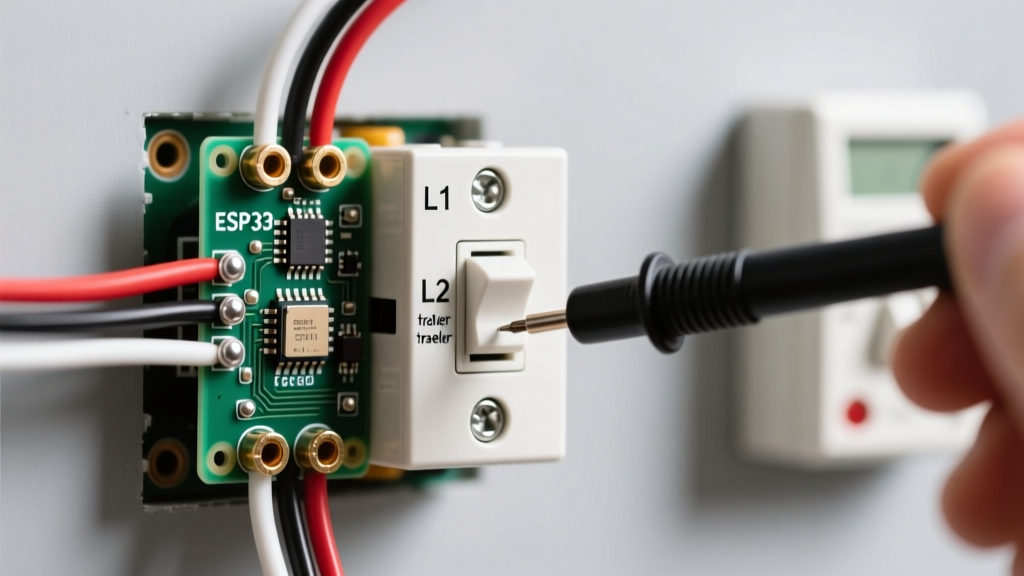
On a standard 3-way switch (e.g., Leviton Decora 5603), there is one dark-colored screw (usually black or dark bronze) known as the "Common" terminal, and two lighter brass-colored screws for the travelers. The Common terminal on Switch A connects to the Line; the Common on Switch B connects to the Load. Visually trace these wires to ensure they match your specific two way electrical switch wiring diagram. If a white wire is used as a Line or Traveler, NEC 2023/2026 requires it to be permanently re-identified with black or red phase tape at both terminations.
Step 3: Continuity Testing the Travelers
With the power OFF and wires disconnected from the switches, set your multimeter to the continuity setting (the diode/soundwave symbol). Place one probe on a traveler wire at Switch A and the other on the corresponding traveler at Switch B. A continuous beep confirms an unbroken path. Repeat for the second traveler. If there is no continuity, you have a broken wire inside the wall cavity, requiring a fishing and rewiring operation.
Step 4: Live Voltage Testing and the "Ghost Voltage" Phenomenon
Reconnect the wires, restore power at the breaker, and set your multimeter to AC Voltage. Test between the Line (Common on Switch A) and the bare ground. You should read 120V (+/- 5V). Now, test the brass traveler terminals. Depending on the toggle positions, one traveler will read 120V, and the other will read 0V.
Expert Troubleshooting Insight: When testing travelers with a high-impedance digital multimeter, you may read a "ghost voltage" of 40V to 80V on the inactive traveler. This is caused by capacitive coupling from the adjacent live traveler wire running in the same Romex cable. To confirm this is a harmless phantom reading and not a dangerous short, switch your multimeter to LoZ (Low Impedance) mode. The ghost voltage will instantly drop to 0V. For more on multimeter techniques, refer to this comprehensive guide on using digital multimeters by Fluke.
Troubleshooting Matrix: Symptoms and Solutions
Use this diagnostic matrix when the physical wiring does not behave as the diagram suggests.
| Symptom | Probable Failure Mode | Testing Action Required |
|---|---|---|
| Light works from Switch A, but Switch B does nothing. | Load wire disconnected at Switch B Common terminal, or failed internal toggle mechanism on Switch B. | Test for 120V at Switch B Common terminal with Switch A toggled ON. If voltage is present but light is off, replace Switch B. |
| Light only turns on when BOTH switches are in the UP position. | Travelers are crossed or misidentified; one traveler is accidentally bonded to ground or neutral. | Perform continuity test on travelers with power OFF. Ensure no continuity exists between travelers and the ground wire. |
| LED bulbs flicker or glow dimly when switches are OFF. | Phantom voltage leaking through illuminated switch locators, or incompatible LED driver. | Measure voltage across the fixture socket with switches OFF. If >2V is present, install a Lutron LUT-MLC bypass capacitor or remove illuminated switches. |
| Breaker trips instantly when toggling Switch B. | Direct short circuit; traveler wire insulation is pierced and touching the ground wire or metal box. | Megohmmeter (Megger) test or standard continuity test between travelers and ground with power OFF and wires disconnected. |
Modernization: Upgrading to Smart Switches in 2026
When inspecting older two-way wiring diagrams, many homeowners ultimately want to upgrade to smart lighting. Standard smart switches (which require a neutral wire) often fail in older 3-way circuits because the switch boxes lack a neutral conductor. The NEC now requires neutrals in almost all new switch boxes, but pre-2011 homes rarely have them.
If your inspection reveals no neutral wire in the switch boxes, you must pivot your upgrade strategy. The Lutron Caseta PD-5WS-DV (approx. $65) is a premier solution that does not require a neutral wire at the switch. However, it requires a proprietary Pico remote to act as the second "switch" location. During your initial diagram inspection, always check for the presence of a white neutral wire bundle capped in the back of the box; its presence or absence will entirely dictate your smart-home upgrade path.
Final Inspection Checklist
Before buttoning up the wall plates, verify the following:
- All bare ground wires are pigtailed and securely fastened to the green grounding screw on both switches and the metal box (if applicable).
- Wire nuts are twisted tightly, and no bare copper is exposed outside the connector.
- Traveler wires are re-identified with yellow or red electrical tape if they are part of a 14/3 or 12/3 Romex cable, aiding future electricians.
- The switch faceplate sits flush against the drywall without cracking the plaster.
By methodically comparing your physical wires to a verified two way electrical switch wiring diagram and utilizing low-impedance testing methods, you eliminate guesswork, ensure code compliance, and guarantee long-term circuit reliability.