
The Hidden Dangers of Degraded Receptacles
An electrical socket outlet is the most frequently used interface in any residential or commercial wiring system. Because they endure constant physical insertion and removal, combined with the thermal cycling of electrical loads, receptacles are prime candidates for mechanical wear and internal connection failures. According to the U.S. Consumer Product Safety Commission (CPSC), faulty receptacles and degraded wiring connections are responsible for thousands of residential fires annually, often stemming from hidden arcing or high-resistance faults that standard circuit breakers cannot detect.
As we navigate the 2026 electrical landscape, modern diagnostics go far beyond simply plugging in a lamp to see if it turns on. Proper inspection requires a systematic approach to verify polarity, ground impedance, voltage stability, and compliance with the latest National Electrical Code (NEC) mandates. This guide provides a master-class protocol for inspecting and testing an electrical socket outlet to uncover hidden hazards before they result in catastrophic failure.
Essential Diagnostic Tools for Professional Testing
To accurately diagnose an electrical socket outlet, you must move past cheap, binary-indicator testers and invest in precision diagnostic equipment. Here is the required toolkit for a comprehensive audit:
- Fluke 117 True-RMS Digital Multimeter ($195 - $220): Essential for measuring exact voltage drops, identifying phantom voltages, and verifying true grounding paths. The True-RMS capability is critical in 2026 due to the prevalence of non-linear loads (LED drivers, smart home hubs) that distort standard sine waves.
- Klein Tools RT250 GFCI Receptacle Tester ($38 - $45): Unlike basic three-light testers, the RT250 features an LCD screen that displays exact wiring faults and includes a built-in solenoid to trip GFCI circuits without relying on the receptacle's internal test button.
- Amprobe INSP-3 Wiring Inspector ($160 - $180): A specialized tool designed to detect 'bootleg' grounds and measure precise ground impedance, which is vital for ensuring sensitive electronics and AFCI breakers function correctly.
- Non-Contact Voltage Tester (NCVT): For initial safety verification before removing the faceplate.
Phase 1: Visual and Physical Inspection Protocol
Before introducing any testing equipment, a rigorous physical inspection of the electrical socket outlet and its surrounding infrastructure is mandatory. Many critical failures are visible to the trained eye.
- Faceplate and Wall Integrity: Check for scorch marks, discoloration, or a melted appearance around the plug slots. This indicates historical overheating, usually caused by a loose internal connection or an overloaded circuit.
- Tamper-Resistant (TR) Verification: Current NEC codes mandate TR receptacles in almost all residential living spaces. Look for the 'TR' stamp on the face. If the outlet is in a dwelling unit and lacks this marking, it is a code violation and requires replacement.
- Paint Overspray and Debris: Paint inside the socket slots can act as an insulator, increasing contact resistance and generating severe heat when a load is applied.
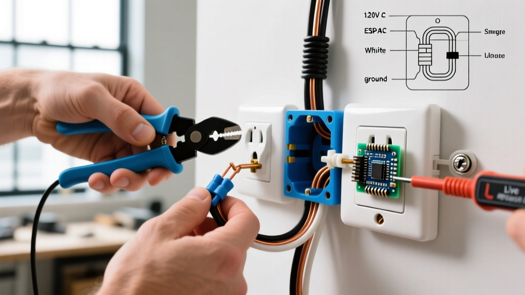
- Termination Method (Backstab vs. Side-Wire): Remove the faceplate and inspect the side of the receptacle. If wires are pushed into the rear 'backstab' holes, the outlet is on borrowed time. Backstabbed connections rely on a small internal spring clamp that loosens over years of thermal expansion and contraction. Expert recommendation: Always replace backstabbed receptacles with new units utilizing side-terminal screw connections or screw-to-clamp yokes.
Phase 2: Voltage and Polarity Testing
Once visual safety is confirmed, proceed to electrical testing. This phase verifies that the electrical socket outlet is delivering power within acceptable tolerances and that the safety ground is legitimate.
Step 1: The Baseline Receptacle Test
Plug the Klein Tools RT250 into the top receptacle. The LCD will immediately identify standard faults such as Open Neutral, Reverse Polarity, or Open Ground. Next, press and hold the GFCI test button for 3-5 seconds. If the outlet is GFCI-protected (either locally or upstream at the breaker), the power should cut. If it does not trip, the GFCI mechanism has failed or is absent, violating NEC requirements for kitchens, bathrooms, laundry areas, and garages.
Step 2: True-RMS Multimeter Verification
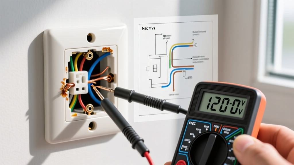
Set your Fluke 117 to AC Voltage (V~). Insert the probes into the receptacle slots to measure the three critical voltage relationships. According to the ANSI C84.1 standard, residential voltage must be maintained within specific tolerances to prevent appliance damage and overheating.
| Measurement Points | Ideal Reading | Acceptable Range (Range A) | Action Required if Outside Range |
|---|---|---|---|
| Line (Hot) to Neutral | 120.0V | 114.0V - 126.0V | Contact utility provider if consistently below 114V or above 126V. |
| Line (Hot) to Ground | 120.0V | 114.0V - 126.0V | If 0V, you have an Open Ground or Hot-Ground Reverse. Immediate repair required. |
| Neutral to Ground | 0.0V - 0.5V | < 2.0V (Under Load) | Readings above 2V indicate a loose neutral connection or overloaded shared neutral. |
Phase 3: Hunting for 'Bootleg' Grounds
One of the most dangerous edge cases encountered when testing an older electrical socket outlet is the 'bootleg' ground. This occurs when a previous DIYer or unscrupulous handyman installs a jumper wire between the neutral terminal and the ground screw on a 2-prong ungrounded circuit to make it appear as a grounded 3-prong outlet.
Warning: A bootleg ground will fool a standard 3-light receptacle tester into showing 'Correct Wiring.' However, if a hot wire faults to the appliance chassis, the chassis becomes energized at 120V, creating a lethal shock hazard because the current has no low-impedance path back to the panel to trip the breaker.
How to test for a bootleg ground:
Plug a high-draw load (like a 1500W space heater) into the bottom receptacle. While the load is running, use your multimeter to measure the voltage between Neutral and Ground on the top receptacle. If the Neutral-to-Ground voltage jumps significantly (e.g., above 3V-5V), the ground is likely tied to the neutral, as the ground path is now carrying the return load current. For definitive proof, turn off the breaker, remove the receptacle, and visually inspect for a jumper wire between the silver (neutral) and green (ground) screws.
Advanced Edge Cases: MWBC and Shared Neutrals
In modern construction and major renovations, you may encounter a Multi-Wire Branch Circuit (MWBC). This setup uses two hot wires (from opposite phases) sharing a single neutral wire to supply multiple electrical socket outlets. While efficient, MWBCs present unique testing anomalies.
If you measure Neutral-to-Ground voltage and find it fluctuating wildly, or if you measure 240V between the hot terminals of two adjacent receptacles, you are likely on an MWBC. The National Fire Protection Association (NFPA) strictly mandates that MWBCs must have a simultaneous disconnect (a double-pole breaker or handle-tied single-pole breakers). If you find an MWBC where the two hot legs are on the same phase (resulting in 0V between hots but double the current on the shared neutral), the neutral wire is at severe risk of melting and causing a fire. This requires immediate panel correction by a licensed electrician.
GFCI and AFCI Nuances in 2026
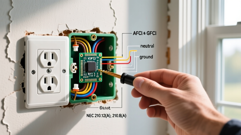
The latest iterations of the NEC have expanded Arc-Fault Circuit Interrupter (AFCI) and Ground-Fault Circuit Interrupter (GFCI) requirements. When testing an electrical socket outlet in a bedroom, living room, or hallway, it must be AFCI protected. Standard receptacle testers cannot verify AFCI functionality reliably. To test AFCI protection, you must use the 'Test' button on the actual circuit breaker in the main panel, as branch-circuit AFCI test buttons on receptacles only test local downstream protection, not the breaker's internal arc-detection algorithms.
Furthermore, Occupational Safety and Health Administration (OSHA) guidelines for commercial and industrial spaces emphasize regular testing of GFCI receptacles in damp locations. GFCI internal circuitry degrades over time due to voltage surges and moisture ingress. An outlet that passed a GFCI test in 2023 may have failed silently by 2026. Monthly manual testing and annual multimeter verification are non-negotiable for commercial compliance.
When to Replace vs. Repair
Not every anomaly requires a full receptacle replacement, but knowing the threshold is critical for safety and cost-efficiency.
- Repair: If the outlet shows correct polarity, proper voltage, and a solid ground, but the faceplate is cracked or the mounting yoke is bent, simply replacing the cover and re-seating the yoke screws is sufficient.
- Replace: If the plug slots feel loose (a plug falls out under its own weight), the internal brass contact springs have lost their tension. This creates high resistance and arcing. Replace the receptacle immediately with a commercial-grade (spec-grade) 20A receptacle, even if on a 15A circuit, as the internal contacts are significantly more robust and durable.
- Rewire: If you discover aluminum wiring (identifiable by its dull grey color and 'AL' stamp on the wire insulation) connected directly to a standard copper-rated receptacle, this is a severe fire hazard. The outlet must be replaced with an AL/CU rated receptacle, or ideally, the connections must be pigtailed to copper using COPALUM or AlumiConn connectors.
Final Verification and Documentation
After any repairs or replacements, re-run the Fluke 117 voltage matrix and the Klein RT250 polarity test. Document the final Neutral-to-Ground voltage readings, especially in areas with sensitive electronics like home offices or entertainment centers. By adhering to this rigorous inspection and testing guide, you ensure that every electrical socket outlet in your system is not only functional but fundamentally safe, code-compliant, and optimized for the electrical demands of the modern era.