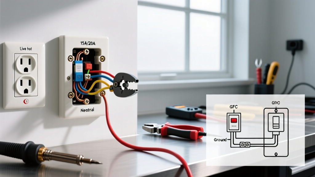

The Definitive Wiring Diagram Reference for Electrical Outlets
Understanding how to wire an electrical outlet requires more than just matching colors; it demands a strict adherence to electrical logic, polarity, and National Electrical Code (NEC) standards. Whether you are replacing a damaged 15-amp duplex receptacle or installing a new 20-amp GFCI in a wet location, a reliable wiring diagram reference is your blueprint for safety and functionality. In this comprehensive guide, we break down the exact terminal mappings, wire gauge requirements, and advanced pigtailing techniques used by licensed electricians in 2026.
Incorrect wiring can lead to reversed polarity, open grounds, or catastrophic thermal failures. According to the U.S. Consumer Product Safety Commission (CPSC), faulty receptacle wiring is a leading cause of residential electrical fires. By treating this guide as your primary diagram reference, you ensure every connection meets the rigorous standards of the NFPA 70 National Electrical Code.
Essential Tools and Safety Protocols
Before consulting any wiring diagram, you must establish a safe work environment. The Occupational Safety and Health Administration (OSHA) mandates strict Lockout/Tagout (LOTO) procedures for all electrical work. Never rely solely on a wall switch to cut power.
- Voltage Tester: Use a non-contact voltage tester (e.g., Klein Tools NCVT-2) to verify the circuit is dead at the breaker, then test the receptacle directly.
- Wire Strippers: Use the precise gauge hole (14 or 12 AWG) to strip exactly 3/4 inch of insulation. Scoring the copper conductor creates a weak point that can snap under terminal torque.
- Torque Screwdriver: A calibrated tool (like the Wiha 61081) is essential. Modern NEC codes heavily emphasize manufacturer torque specifications to prevent thermal loosening over time.
Wire Gauge and Breaker Sizing Matrix
A wiring diagram is useless if the foundational circuit parameters are incorrect. You must match the receptacle rating, wire gauge, and overcurrent protection device (breaker). The table below serves as your quick-reference matrix for standard residential branch circuits.
| Circuit Rating | Wire Gauge (Copper) | Breaker Size | Receptacle Type | Common Applications |
|---|---|---|---|---|
| 15 Amp | 14 AWG | 15A | 15A Duplex (NEMA 1-15R) | Bedrooms, Living Rooms, Hallways |
| 20 Amp | 12 AWG | 20A | 20A Duplex (NEMA 5-20R) or 15A Duplex | Kitchens, Bathrooms, Garages, Outdoors |
| 20 Amp GFCI | 12 AWG | 20A | 20A GFCI (NEMA 5-20R) | Countertops, Wet Bars, Unfinished Basements |
Note: While 15A receptacles are legally permitted on 20A circuits (provided there is more than one receptacle on the yoke), using 12 AWG wire on a 15A breaker is a common best practice for future-proofing and minimizing voltage drop over long runs.
Standard 15A and 20A Duplex Receptacle Wiring
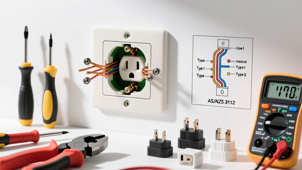
The standard duplex receptacle (such as the Leviton Decora 05320-WMP) features four terminal screws and a grounding screw. Here is the universal diagram logic for a standard feed-through installation:
Terminal Mapping Guide
- Ungrounded Conductor (Hot): The black (or red) wire connects to the brass-colored screw. This is the line-side hot.
- Grounded Conductor (Neutral): The white wire connects to the silver-colored screw.
- Equipment Grounding Conductor: The bare copper or green wire connects to the green grounding screw at the bottom of the yoke.
The Break-Off Fin (Split-Wired Outlets)
On the brass (hot) side of the receptacle, you will notice a small metal tab connecting the top and bottom screws. In a standard wiring diagram, this tab remains intact. However, if you are wiring a split-receptacle (where the top half is controlled by a wall switch and the bottom half is always hot), you must use needle-nose pliers to snap this brass tab off. Never break the silver (neutral) tab unless you are dealing with a highly specific multi-wire branch circuit (MWBC) setup, which requires a double-pole breaker.
The Pigtailing Method vs. Feed-Through Wiring
When wiring multiple outlets in a daisy-chain configuration, novice DIYers often use the receptacle itself to pass power to the next box by connecting two black wires to the top brass screw and two white wires to the top silver screw. This is known as 'feed-through' wiring and is widely discouraged by master electricians.
Expert Insight: If a feed-through receptacle fails or is removed for replacement, every outlet downstream loses power, including its neutral path. An open neutral on a multi-wire branch circuit can send 240V through 120V appliances, destroying electronics. Always use the pigtailing method.
How to Execute a Proper Pigtail
Pigtailing involves connecting all incoming and outgoing hot wires together with a short 'pigtail' wire that runs to the receptacle screw. In 2026, the industry standard for pigtailing has shifted from traditional twist-on wire nuts to lever connectors.
- Wago 221-412 Lever Nuts: Ideal for joining two 12 AWG or 14 AWG solid wires with a pigtail. They provide a transparent housing for visual inspection and maintain consistent clamping pressure.
- Ideal Industries Power Plug: Excellent for pushing in pre-stripped solid wires when space in the junction box is severely limited.
GFCI Receptacle Wiring: Line vs. Load
Ground Fault Circuit Interrupter (GFCI) receptacles are mandated by NEC Article 210.8 in all wet or damp locations. Wiring a GFCI (like the Eaton GFTR15W) introduces a critical diagram variable: LINE vs. LOAD.
Identifying Line and Load
The back of a GFCI receptacle is divided into two distinct sections:
- LINE: This is where the incoming power from the breaker panel connects. Black to brass, white to silver.
- LOAD: This section protects downstream standard receptacles. If you want a standard outlet in the same bathroom to be protected by this GFCI, the wires feeding that downstream outlet must connect to the LOAD terminals.
Pro-Tip: GFCI receptacles often come with a piece of yellow tape covering the LOAD terminals. Do not remove this tape unless you are actively wiring downstream devices. Connecting incoming power to the LOAD terminals will result in a receptacle that has power but will immediately trip or fail to reset.
Advanced Pro-Tips: Torque and Back-Wiring
The physical method of terminating wires is just as critical as the diagram logic. Receptacles generally offer three termination methods:
| Termination Type | Mechanism | Reliability Rating | Electrician Consensus |
|---|---|---|---|
| Push-In (Backstab) | Spring-loaded friction grip | Poor | Avoid entirely. Prone to thermal expansion failures and arcing. |
| Side-Wiring | Wire wrapped around screw head | Good | Acceptable, but wire can slip out if not looped clockwise. |
| Back-Wiring (Clamp) | Screw tightens a metal plate over wire | Excellent | Industry standard for commercial and high-end residential. |
When using side-wiring or back-wiring with a clamp plate, you must adhere to the manufacturer's torque specifications. For most 15A and 20A Leviton and Eaton receptacles, the required torque is 14 in-lbs. Under-torquing leads to high-resistance connections that generate heat; over-torquing can strip the brass threads or crush the copper conductor.
Troubleshooting Common Wiring Faults
After completing your wiring based on the diagram, always test the receptacle with a solenoid tester or a digital receptacle analyzer like the Klein Tools RT250. Below is a diagnostic matrix for common faults.
| Tester Reading | Probable Cause | Diagram Correction |
|---|---|---|
| Open Ground | Ground wire disconnected or broken. | Verify bare copper is securely clamped under the green screw and bonded to the metal box (if applicable). |
| Reversed Polarity | Hot and neutral swapped. | Move black wire to brass screw and white wire to silver screw. Never rely on wire color alone; always verify with a multimeter. |
| Hot/Ground Reverse | Bootleg ground or severe miswire. | Check for a jumper wire between the hot brass screw and the green ground screw. Remove immediately. |
| Open Neutral | Neutral path broken upstream. | Check wire nuts in the junction box. Ensure white wires are not just touching, but securely twisted and capped. |
Final Code Compliance Checks for 2026
As you finalize your installation, ensure your setup aligns with the latest code adoptions. NEC 406.12 requires all 15A and 20A receptacles in dwelling units to be Tamper-Resistant (TR), featuring internal shutters that prevent foreign objects from being inserted. Furthermore, AFCI (Arc Fault Circuit Interrupter) protection is now broadly required in almost all living spaces, while GFCI protection is strictly enforced in kitchens, bathrooms, garages, outdoors, and within 6 feet of any wet bar sink. By combining this wiring diagram reference with rigorous testing and code compliance, you guarantee a safe, durable, and fully functional electrical system.