
Understanding the Australia Electrical Outlet Standard
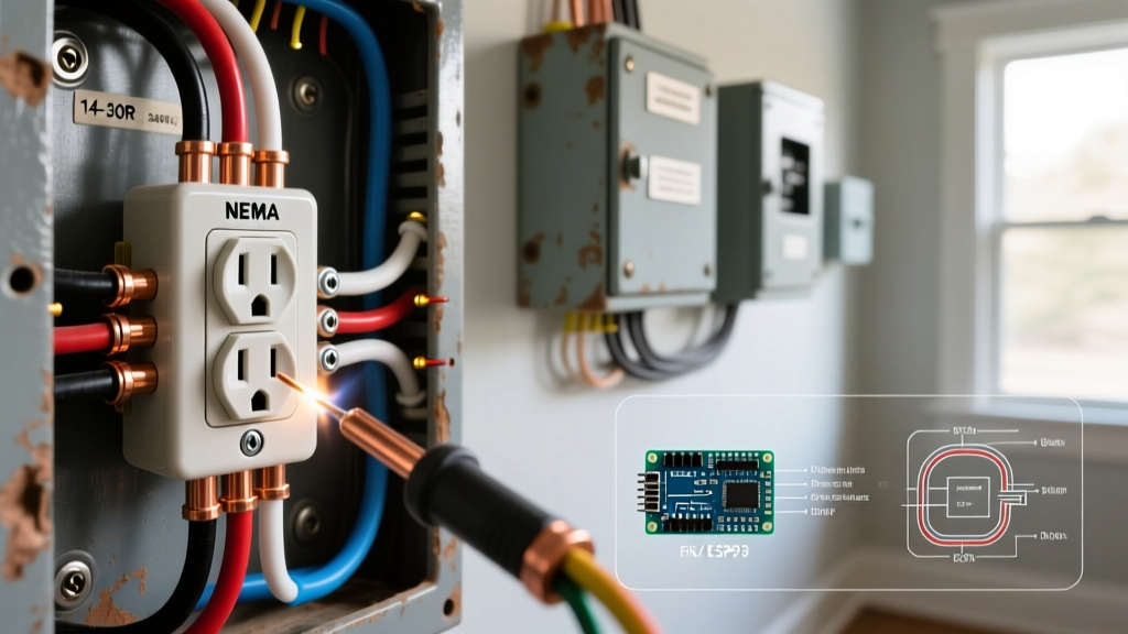
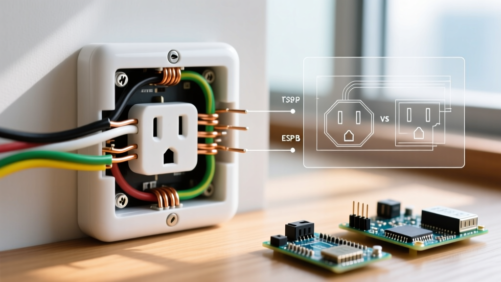
The Australia electrical outlet, universally recognized as the Type I configuration, operates on a nominal 230V AC supply at 50Hz. Governed strictly by the AS/NZS 3112 standard for plug and socket-outlet dimensions, and the AS/NZS 3000 Wiring Rules for installation and testing, these outlets feature three flat pins arranged in an inverted triangular pattern, complete with insulated active and neutral pins to prevent accidental shock during partial insertion. For DIY enthusiasts, electricians, and facility managers, routine inspection and testing of these power points are not just best practices—they are critical legal and safety requirements. In 2026, with the increasing prevalence of high-draw EV chargers and smart home integrations plugged into standard 10A and 15A circuits, ensuring the integrity of every Australia electrical outlet is paramount.
Mandatory Tools for AS/NZS 3000 Compliance Testing
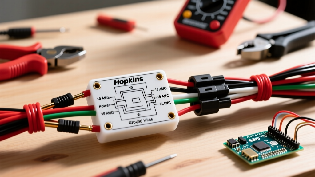
Before touching a faceplate, you must equip yourself with calibrated, category-rated testing instruments. Relying on a basic voltage pen is insufficient and highly dangerous for comprehensive outlet diagnostics. According to Safe Work Australia, only properly rated and maintained test equipment should be used for electrical verification.
- Fluke T6-1000 PRO Electrical Tester (~$380 AUD): Essential for non-contact voltage detection and OpenJaw current measurements without disconnecting the outlet.
- Martindale EZ150 Socket Tester (~$95 AUD): A quick-check device for verifying basic polarity, earth presence, and RCD trip functionality on standard 10A Australia electrical outlets.
- Megger MIT420/2 Insulation Tester (~$1,450 AUD): Required for dead-testing insulation resistance at 250V and 500V DC to ensure the dielectric integrity of the branch circuit wiring.
- Kyoritz KEW 6516 PAT Tester (~$1,200 AUD): Used for portable appliance testing, which includes verifying the earth continuity and leakage current of devices plugged into the outlet.
Phase 1: Visual and Mechanical Inspection
Electrical faults often manifest physically before they cause a catastrophic failure. A rigorous visual inspection of the Australia electrical outlet and its surrounding architrave can reveal severe underlying issues. Use the following checklist to identify physical defects:
| Defect Symptom | Potential Root Cause | Required Action |
|---|---|---|
| Scorch marks around the earth pin slot | High resistance connection due to loose terminal screws or oxidized copper. | Isolate circuit, re-terminate wires, and replace the socket mechanism. |
| Faceplate loose or bowing outward | Overcrowded backbox, missing mounting screws, or thermal expansion damage. | Verify backbox depth (minimum 25mm for standard wiring) and secure flush. |
| Safety shutters fail to open evenly | Mechanical wear, debris ingress, or use of non-compliant foreign adapters. | Replace the entire socket outlet; do not attempt to lubricate or force shutters. |
| Cracked or brittle bakelite/polycarbonate | UV degradation (if exposed to sunlight) or prolonged thermal overload. | Immediate replacement with a UV-rated or heavy-duty industrial outlet. |
Phase 2: Dead Testing (Isolation Required)
Dead testing must only be performed after the circuit has been isolated at the main switchboard, locked out (LOTO), and proven dead using a proven voltage indicator. Never assume an Australia electrical outlet is de-energized simply because the switch is in the 'OFF' position.
1. Earth Continuity Testing
Using a low-resistance ohmmeter, measure the continuity between the outlet's earth pin and the main earth bar in the switchboard. The AS/NZS 3000 standard mandates that the resistance of the protective earthing conductor must be sufficiently low to allow fault currents to trip the protective device. For a standard 2.5mm² copper branch circuit, expect a reading well below 0.5 ohms. Any reading above 1.0 ohm indicates a compromised earth path, possibly due to a broken strand or a corroded connection at the outlet's earth terminal.
2. Insulation Resistance (IR) Testing
Set your Megger to 500V DC. Test between Active and Earth, and then Neutral and Earth. The minimum acceptable insulation resistance for a standard domestic final subcircuit is 1 Megohm (1,000,000 ohms). If you record a reading between 0.5MΩ and 1.0MΩ, the wiring may be degraded by moisture, rodent damage, or thermal aging, requiring further investigation. A reading below 0.5MΩ is an immediate fail, indicating a direct leakage path that could cause nuisance RCD tripping or shock hazards.
Expert Note on Wiring Colors: When opening an older Australia electrical outlet, you may encounter the legacy color code: Red (Active), Black (Neutral), and Green (Earth). Post-2010 harmonized installations must use Brown (Active), Blue (Neutral), and Green/Yellow (Earth). If you are replacing an outlet in a mixed-color circuit, meticulously sleeve the old wires with the correct harmonized colored tubing to prevent future maintenance hazards.
Phase 3: Live Testing and Earth Loop Impedance
Once dead testing is complete and the outlet is reassembled, restore power to conduct live verification. Live testing confirms the outlet's behavior under operational conditions and verifies the speed of the protective devices.
Polarity and Voltage Verification
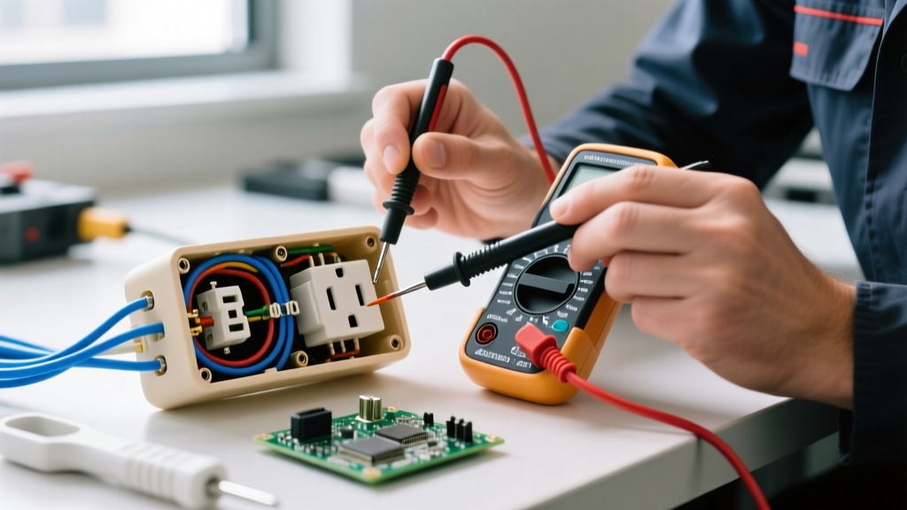
Insert your socket tester or multimeter probes. Verify that the Active is on the right (when viewing the outlet with the earth pin at the top), the Neutral is on the left, and the Earth is at the top. Measure the line-to-neutral voltage; in Australia, this should read between 216V and 253V (230V +10%/-6%). A reading outside this band indicates a supply issue or severe voltage drop along an undersized or overly long cable run.
Earth Loop Impedance (Zs) Measurement
The Earth Loop Impedance (Zs) is the total impedance of the fault loop path, from the transformer, through the active conductor, through the fault, and back via the earth conductor. Using a dedicated loop impedance tester, trigger a high-current test (if the RCD allows) or a low-current no-trip test. For a 20A Type C circuit breaker protecting a 2.5mm² cable, the maximum permissible Zs is typically around 1.15 ohms to ensure the breaker trips within the required 0.4 seconds during a fault. High Zs values mean the breaker will not trip fast enough, leaving the Australia electrical outlet energized during a short circuit.
RCD (Safety Switch) Integration and Trip Testing
Under AS/NZS 3000:2018 (and its subsequent amendments), virtually all final subcircuits, including those supplying standard power points, must be protected by a 30mA Residual Current Device (RCD). Testing the RCD directly from the outlet is a critical compliance step.
- 1x IΔn Test (30mA): Inject a 30mA fault current. The RCD must trip within 300 milliseconds.
- 5x IΔn Test (150mA): Inject a 150mA fault current. The RCD must trip within 40 milliseconds to prevent ventricular fibrillation in a human subject.
- Ramp Test: Slowly increase the leakage current from 0mA. A healthy Type I or Type II RCD should trip between 15mA and 30mA. If it trips below 15mA, it is overly sensitive and prone to nuisance tripping; if it fails to trip at 30mA, it is defective and must be replaced immediately.
For modern installations featuring solar inverters or EV chargers plugged into the Australia electrical outlet, ensure the circuit is protected by a Type F or Type B RCD, as standard Type AC RCDs can be blinded by smooth DC residual currents generated by modern power electronics.
Troubleshooting Matrix: Common Outlet Faults
When an Australia electrical outlet fails to perform, use this diagnostic matrix to isolate the issue rapidly.
| Observed Symptom | Diagnostic Test | Likely Culprit |
|---|---|---|
| Outlet dead, but breaker is ON | Check voltage at terminals; verify upstream daisy-chain connections. | Broken active/neutral conductor in a loop-in/loop-out junction or loose terminal. |
| RCD trips instantly when appliance is plugged in | Perform Insulation Resistance test on the appliance and the outlet wiring. | Appliance earth leakage, or neutral-to-earth fault in the branch wiring. |
| Voltage drops to 190V under load | Measure voltage at the switchboard vs. the outlet while running a 2kW heater. | Undersized cable run (e.g., 1.5mm² used instead of 2.5mm²) or loose neutral busbar. |
| Outlet feels warm to the touch | Use thermal camera; check terminal torque. | Sustained overload (drawing >10A continuously) or high-resistance termination. |
Documentation, Tagging, and Final Sign-Off
Testing an Australia electrical outlet is only half the battle; documenting the results ensures ongoing compliance and liability protection. For commercial or industrial environments, every tested outlet and connected appliance must be logged in a digital or physical register. If conducting Portable Appliance Testing (PAT), apply a color-coded 'Test and Tag' label indicating the test date, the tester's license number, and the next due date. According to Energy Safe Victoria, maintaining rigorous records of electrical maintenance and testing is a core component of a site's electrical safety management system.
For residential DIYers, keep a logbook of your multimeter readings, particularly Earth Loop Impedance and Insulation Resistance values, to establish a baseline. If future readings deviate significantly from your 2026 baseline, you will know that environmental factors or physical degradation are compromising the circuit. For further reading on consumer product safety and recalling faulty electrical accessories, always consult the ACCC Electrical Safety database before purchasing replacement outlet mechanisms. By adhering to these rigorous inspection and testing protocols, you ensure that every Australia electrical outlet in your facility remains a safe, reliable, and compliant power source.