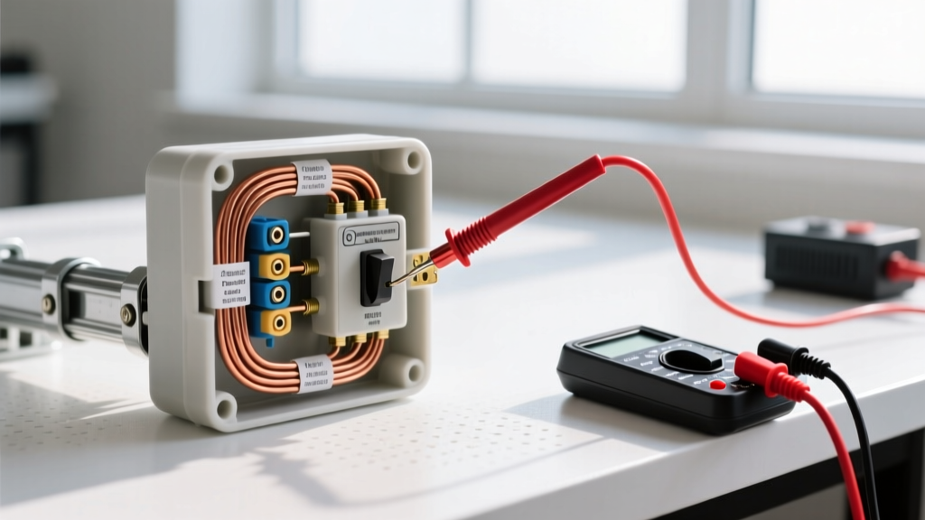

The Critical Role of the Electric Trailer Jack Switch Circuit
When your A-frame electric trailer jack fails to lift or lower, the immediate suspect is often the motor. However, in over 65% of field failures involving popular models like the Lippert 3500-lb Power Tongue Jack (Model 1817941) or the Husky Super Brute (Model HB4500), the root cause lies within the switch circuit or grounding path. Because these 12V DC motors draw upwards of 30 amps under peak load, the wiring and switch components are subjected to extreme thermal and electrical stress. Understanding the electric trailer jack switch wiring diagram is not just about installation; it is the foundational blueprint for systematic inspection, voltage drop testing, and fault isolation.
In this 2026 inspection and testing guide, we will bypass generic troubleshooting advice and dive deep into the exact multimeter procedures, circuit specifications, and failure modes required to diagnose your trailer jack switch wiring. Whether you are dealing with a melted DPDT (Double Pole Double Throw) rocker switch or a hidden galvanic corrosion issue on the ground ring terminal, this guide provides the actionable data you need.
Safety Warning: Always disconnect the negative battery terminal before performing continuity tests or modifying the switch housing. A 12V DC circuit at 30 amps can sustain a severe arc flash capable of welding metal tools and causing second-degree burns. Use insulated tools and wear safety glasses when probing live terminals.
Anatomy of a Standard 12V Electric Jack Switch Circuit
Before grabbing your digital multimeter (DMM), you must visualize the current flow. A standard electric trailer jack does not use a simple single-pole on/off switch. To reverse the motor direction (up and down), the circuit utilizes a DPDT rocker switch or a relay-based control board. This switch reverses the polarity of the 12V DC current sent to the motor's two brushes.
Core Circuit Components
- Power Source: 12V deep-cycle marine or RV battery.
- Overcurrent Protection: 30A Type 1 auto-reset circuit breaker (typically mounted within 18 inches of the battery positive terminal, per RVIA and NEC guidelines).
- Switch Mechanism: 12V DPDT rocker switch with 6 spade terminals, or a solid-state relay board.
- Conductors: 10 AWG stranded copper wire for the main power and ground; 12 AWG or 14 AWG for relay trigger wires on upgraded models.
- Ground Path: The outer steel tube of the jack assembly, grounded via a star washer and ring terminal bolted directly to the A-frame trailer tongue.
Decoding the Electric Trailer Jack Switch Wiring Diagram
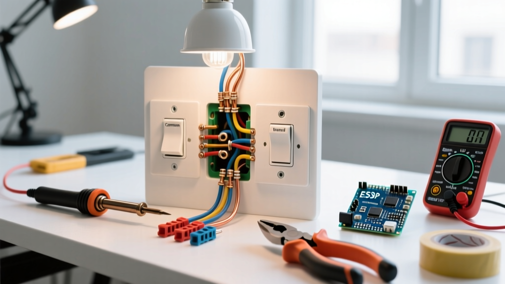
The wiring diagram for these systems relies on a specific color code and terminal layout. When inspecting the back of the DPDT switch, you will see six terminals. The power input from the 30A breaker feeds the center terminals, while the top and bottom terminals route to the motor brushes. Flipping the switch cross-connects the polarity, reversing the motor.
| Circuit Segment | Standard Wire Color | Wire Gauge | Target Testing Parameter |
|---|---|---|---|
| Battery to Breaker | Red (or Black with Red trace) | 10 AWG | Continuity < 0.1 Ohms |
| Breaker to Switch Input | Red | 10 AWG | Voltage Drop < 0.3V under load |
| Switch Output to Motor | Red / Black (Polarity pair) | 10 AWG | 12.2V - 12.6V (Resting) |
| Motor Ground to Chassis | Bare Copper / White | 10 AWG | Voltage Drop < 0.2V under load |
Step-by-Step Inspection & Multimeter Testing Guide
To accurately diagnose the circuit, we use a systematic voltage drop and continuity approach. For this procedure, a high-impedance DMM like the Fluke 87V or Fluke 117 is recommended. According to Fluke's electrical testing guidelines, voltage drop testing under load is the only reliable way to identify high-resistance faults that a standard continuity test will miss.
Phase 1: Visual Inspection & Mechanical Verification
- Inspect the Auto-Reset Breaker: Locate the 30A breaker near the battery. Look for signs of thermal melting on the plastic housing or corrosion on the copper studs. If the breaker is hot to the touch after a single jack cycle, the motor is binding or the breaker is undersized.
- Check the Ground Star Washer: The ground wire connects the jack motor housing to the trailer frame. Remove the bolt and inspect the star washer. If the washer has not bitten through the paint and powder coating down to bare steel, the circuit is relying on parasitic ground paths, leading to severe voltage drops.
- Examine the DPDT Spade Connectors: Pull the female spade connectors off the back of the rocker switch. Look for black soot (arcing) or melted plastic. High amperage passing through cheap, un-crimped spade connectors generates massive heat.
Phase 2: Voltage Drop Testing Under Load
A static voltage test will not reveal a failing wire or corroded terminal. You must test the circuit while the motor is actively trying to lift the trailer tongue.
- Set your DMM to DC Volts.
- Place the red probe on the positive battery terminal and the black probe on the input terminal of the DPDT switch.
- Activate the switch to raise the jack. The meter should read less than 0.3V. If it reads 1.5V or higher, you have high resistance in the 10 AWG power wire or the 30A breaker is failing internally.
- Next, test the ground side. Place the red probe on the negative battery terminal and the black probe on the bare metal housing of the jack motor. Activate the switch. A reading above 0.2V indicates a failed chassis ground connection.
Phase 3: Bypassing the Switch to Isolate the Motor
If the switch receives 12.6V but the motor does not run, you must determine if the switch internals are burnt or if the motor brushes are dead. Using a heavy-duty 10 AWG jumper wire, bypass the DPDT switch entirely. Connect the jumper directly from the breaker output to the motor's positive terminal. If the motor engages immediately, the DPDT switch has failed internally and must be replaced. If the motor still does not run, the issue is internal to the motor (e.g., worn carbon brushes or a seized planetary gear).
Common Failure Modes & Edge Cases
When cross-referencing the electric trailer jack switch wiring diagram with field data, several recurring edge cases emerge that confuse DIY mechanics:
- The 'Click-But-No-Move' Syndrome: You hear a distinct click from the switch or relay, but the motor does not turn. This is almost never an electrical switch failure. It is usually a sheared roll pin inside the jack's gear housing, or the motor's internal thermal overload switch has tripped due to prolonged cranking. Wait 10 minutes for the thermal switch to reset.
- Galvanic Corrosion on the Ground Path: Because the jack tube sits inside an aluminum or steel A-frame bracket, dissimilar metals and road salt create galvanic corrosion. This acts as an invisible resistor. Even if the wiring diagram shows a solid ground, the physical metal-to-metal contact may be compromised. Always use a dedicated 10 AWG ground wire run directly back to the battery negative terminal if chassis grounding proves unreliable.
- Parasitic Battery Draw: Some older jack models wire the switch directly to the battery without a master disconnect. If the DPDT switch accumulates internal carbon tracking from arcing, it can create a micro-short, draining your battery over a week of storage. Installing a marine-grade battery disconnect switch is highly recommended.
Upgrading the Switch Circuit for Heavy-Duty Use
Routing 30 amps of continuous DC current through a standard $12 plastic DPDT rocker switch is an inherent design flaw in many entry-level trailer jacks. The NEC and RV industry standards, as outlined in NFPA 70 (National Electrical Code) Article 551 regarding recreational vehicle low-voltage systems, emphasize minimizing thermal risks in high-amperage DC circuits.
For heavy-duty applications, or if you frequently tow in cold weather where motor amperage spikes due to thickened gearbox grease, upgrade your wiring diagram to utilize a 12V Continuous Duty Solenoid (such as the Cole Hersee 24059 or Trombetta 974). In this upgraded diagram, the heavy 10 AWG power wire routes directly from the battery, through the 30A breaker, into the solenoid, and straight to the motor. The DPDT rocker switch is moved to a low-amperage trigger circuit (using 16 AWG wire) that simply activates the solenoid's electromagnetic coil. This keeps 30 amps of heat-generating current out of the switch housing entirely, virtually eliminating melted switch failures and extending the lifespan of your trailer jack electronics.
Final Verification & Maintenance
After completing your inspection and executing any necessary repairs based on the wiring diagram, perform a full load test. Apply a dielectric grease (like NOALOX or standard silicone dielectric grease) to all spade connectors and the ground ring terminal to prevent future moisture ingress. According to comprehensive trailer wiring resources like etrailer's technical FAQ database, applying dielectric grease to 12V DC outdoor connections is the single most effective preventative measure against high-resistance voltage drops. By treating your electric trailer jack switch circuit with the same diagnostic rigor as a household AC panel, you ensure reliable, safe, and consistent operation on every camping trip or job site deployment.