
Why Upgrade Your Industrial Electrical Outlet?
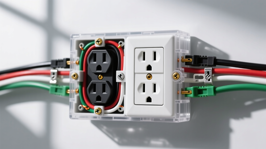
Upgrading an industrial electrical outlet is rarely a cosmetic endeavor. In manufacturing plants, commercial workshops, and heavy-duty construction sites, power receptacles endure extreme mechanical stress, thermal cycling, and environmental exposure. Unlike standard residential 15A or 20A duplex receptacles, industrial outlets—primarily NEMA twist-lock and IEC 60309 pin-and-sleeve configurations—are engineered to maintain continuous contact pressure under heavy inductive loads. However, even the most robust Hubbell or Bryant receptacles degrade over time. Recognizing the failure modes and executing a precision replacement is critical for maintaining operational uptime and ensuring compliance with modern electrical codes.
Primary Failure Modes in Heavy-Duty Receptacles
- Thermal Degradation: Repeated high-current draws cause micro-arcing at the terminal blades, leading to localized melting of the thermoset or nylon housing. If the faceplate shows brown or black scorch marks, immediate replacement is mandatory.
- Contact Tension Loss: The internal brass or phosphor-bronze contacts lose their spring tension after hundreds of mating cycles. This increases contact resistance, generating excess heat (I²R losses) that can trip upstream thermal-magnetic breakers prematurely.
- Environmental Ingress: In washdown or outdoor environments, compromised weatherproof boots allow moisture to bridge the phase and ground terminals, leading to ground faults or catastrophic short circuits.
NEMA Twist-Lock and Pin-and-Sleeve Configuration Matrix
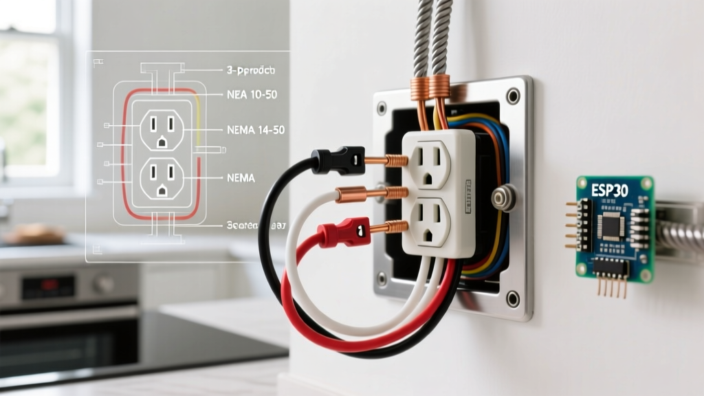
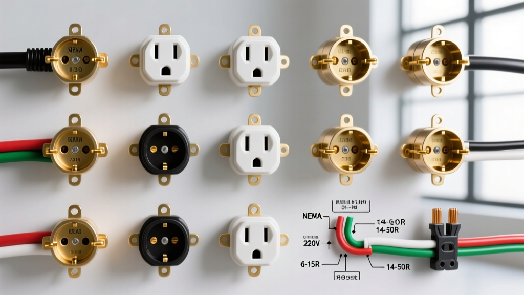
Before initiating a replacement, you must verify the exact NEMA or IEC configuration. Mismatching a plug and receptacle, or attempting to adapt a 3-phase load to a single-phase outlet, violates NEMA WD 6 Wiring Devices dimensional standards and poses severe safety hazards. Below is a comparison of the most common industrial configurations encountered in 2026.
| NEMA / IEC Config | Voltage & Phase | Amps | Common Application | Reference Model | Est. 2026 Price |
|---|---|---|---|---|---|
| NEMA L6-30R | 250V, 1-Phase | 30A | Welders, heavy compressors, server racks | Hubbell HBL2620 | $85 - $110 |
| NEMA L14-30R | 125/250V, 1-Phase | 30A | Backup generators, transfer switches | Hubbell HBL2720 | $95 - $125 |
| NEMA L15-30R | 250V, 3-Phase | 30A | CNC machinery, industrial HVAC, motors | Hubbell HBL2420 | $110 - $145 |
| NEMA 14-50R | 125/250V, 1-Phase | 50A | EV charging stations, temporary power distros | Leviton 278-S00 | $75 - $95 |
| IEC 60309 (Pin & Sleeve) | 200-250V, 1-Phase | 32A | Food processing, wet/washdown environments | Mennekes 2146 | $130 - $180 |
Step-by-Step Industrial Receptacle Replacement Protocol
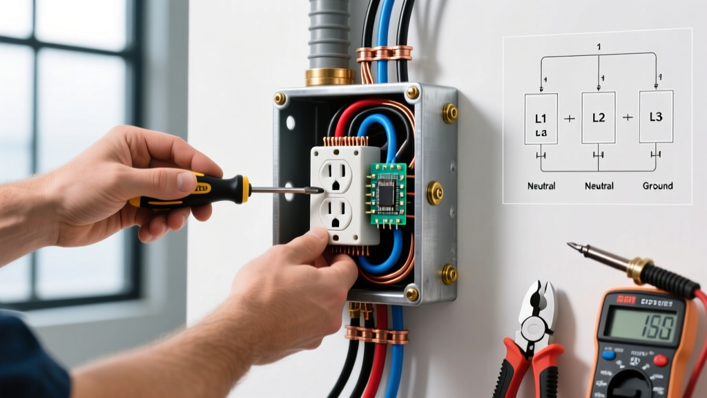
Replacing an industrial electrical outlet requires strict adherence to safety protocols and precise mechanical terminations. Follow this standardized procedure to ensure a reliable, code-compliant installation.
Step 1: Execute Lockout/Tagout (LOTO)
Never rely solely on a wall switch or a machine's power button. You must isolate the circuit at the main distribution panel and apply a physical lock and tag. According to OSHA's Control of Hazardous Energy guidelines, failing to properly execute LOTO is one of the most frequently cited violations in industrial settings and carries a high risk of fatal arc flash incidents.
Step 2: Verify Absence of Voltage (Live-Dead-Live Test)
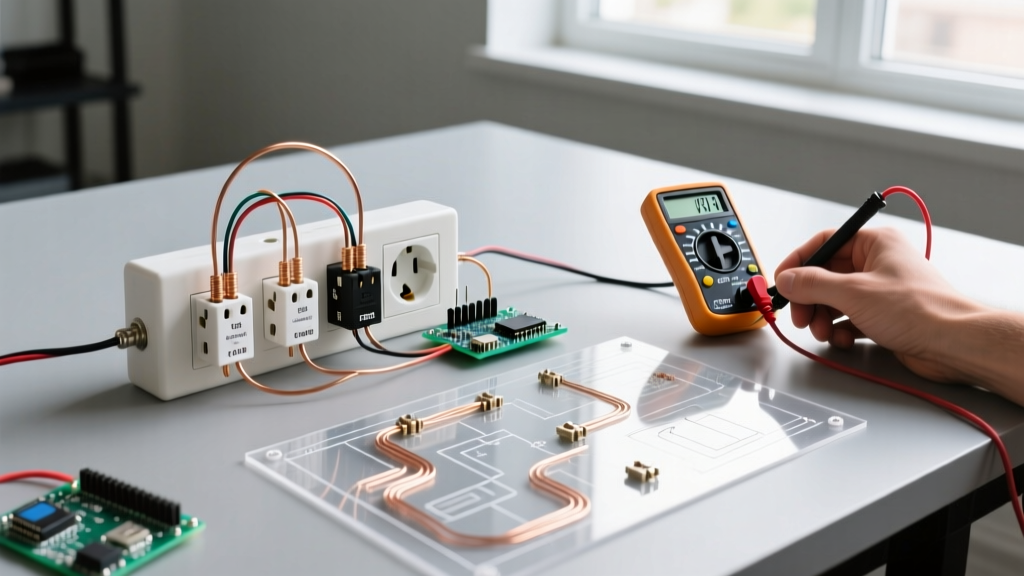
Using a CAT III or CAT IV rated digital multimeter (such as the Fluke 87V), test the existing receptacle.
- Test the meter on a known live source (Live).
- Test the target industrial outlet phase-to-phase, phase-to-neutral, and phase-to-ground (Dead).
- Re-test the meter on the known live source to ensure the meter did not fail during the process (Live).
Step 3: Conductor Preparation and Stripping
Industrial circuits typically utilize #10 AWG to #6 AWG THHN/THWN-2 conductors. Use a precision wire stripper to avoid nicking the copper, which creates a weak point prone to snapping under thermal expansion.
- #10 AWG: Strip exactly 3/4 inch of insulation.
- #8 AWG: Strip exactly 7/8 inch of insulation.
- #6 AWG: Strip exactly 1 inch of insulation.
Step 4: Torque-Specified Terminations
This is where most DIY and amateur industrial upgrades fail. Hand-tightening terminal screws is unacceptable for high-amperage circuits. You must use a calibrated torque screwdriver. For a standard 30A twist-lock receptacle terminating #10 AWG copper wire, the manufacturer specification is typically 45 to 50 inch-pounds. Under-torquing leads to loose connections and arcing; over-torquing strips the brass threads or crushes the wire strands, reducing the effective cross-sectional area and increasing resistance.
Step 5: Weatherproof Enclosure Sealing
If the outlet is located in a damp or wet environment, install a die-cast aluminum weatherproof box with an IP67-rated in-use cover. Apply a continuous bead of silicone RTV sealant around the conduit hubs to prevent moisture migration into the junction box.
2026 Code Compliance: GFCI and EFPD Mandates
NEC Update Alert: As of the 2023 NEC (and carried forward into the 2026 adoption cycles across most US jurisdictions), Article 406.3(E) mandates Ground-Fault Circuit-Interrupter (GFCI) protection for all non-locking 15A and 20A, 125V and 250V receptacles in industrial settings. Furthermore, for 3-phase industrial electrical outlets rated 15A to 100A, Equipment Ground Fault Protection (EGFP) or advanced GFCI integration is increasingly required to protect personnel from lethal ground faults.
When upgrading older 3-phase machinery outlets, consider installing integrated GFCI twist-lock receptacles (such as the Leviton SmartlockPro series) or upgrading the upstream breaker to an EGFP model. This ensures compliance without requiring a complete overhaul of the facility's wiring infrastructure.
Assured Equipment Grounding Conductor Program (AEGCP)
In temporary industrial settings and construction sites, OSHA regulation 1926.404(b)(1) requires an AEGCP if GFCI protection is not utilized on all 120V, single-phase, 15A and 20A receptacles. When replacing outlets in these environments, the site safety officer must log the new receptacle into the AEGCP testing schedule. This requires a daily visual inspection and a quarterly continuity test using a specialized ground impedance tester to verify that the equipment grounding conductor (EGC) provides a low-impedance path back to the source.
Post-Installation Troubleshooting Matrix
After completing the upgrade and restoring power, perform a functional load test. If anomalies occur, consult this diagnostic matrix:
| Symptom | Probable Cause | Corrective Action |
|---|---|---|
| Upstream breaker trips immediately upon plugging in the load. | Phase-to-Ground short; incorrect wiring of the W (Ground) and X/Y (Phase) terminals. | Re-verify LOTO. Open receptacle and confirm the green grounding screw is connected exclusively to the bare/green EGC. |
| Receptacle faceplate becomes hot to the touch after 20 minutes of load. | Under-torqued terminal screws; stranded wire splaying outside the terminal clamp. | Perform a thermal scan with an IR camera. Re-terminate wires, ensuring all strands are captured, and torque to 50 in-lbs. |
| Connected 3-phase motor runs in reverse or hums without starting. | Phase rotation is incorrect; two phase conductors are swapped on the receptacle terminals. | Swap any two of the three phase conductors (X and Y) at the receptacle terminals to reverse the phase sequence. |
| Voltage reads 120V phase-to-ground, but 208V phase-to-phase (on a 240V system). | Connected to a 208Y/120V 3-phase wye panel instead of a 240V delta or split-phase panel. | Verify the source panel voltage. Replace the receptacle with a 208V-rated model or re-route the circuit to the correct 240V distribution panel. |
Final Thoughts on Industrial Outlet Maintenance
An industrial electrical outlet is the critical handoff point between your facility's fixed wiring and your mobile, high-draw equipment. By prioritizing torque-specific terminations, adhering to modern GFCI mandates, and selecting premium NEMA or IEC configurations from trusted manufacturers, you eliminate the hidden costs of downtime and electrical fires. Always document your upgrades in the facility's electrical one-line diagram and schedule annual thermal imaging inspections to catch contact degradation before it results in a catastrophic failure.