
Decoding the Electrical Switch Wiring Diagram
Reading an electrical switch wiring diagram is a foundational skill for any DIYer or apprentice electrician. However, schematic symbols on paper rarely match the chaotic reality of a crowded junction box. In 2026, with the proliferation of Matter-over-Thread smart home devices and stricter National Electrical Code (NEC) box-fill requirements, understanding the physical translation of these diagrams is more critical than ever. A misinterpreted traveler wire or a missing neutral connection can result in tripped breakers, fried smart switches, or severe arc faults.
This guide bypasses generic theory and dives directly into five common wiring scenarios. We will decode the schematics, specify exact terminal connections, and provide the professional-grade torque and stripping measurements required for a safe, code-compliant installation.
Scenario 1: The Standard Single-Pole Switch (SPST)
The single-pole switch is the baseline of residential lighting. The schematic represents a Single-Pole Single-Throw (SPST) switch, simply breaking or completing the hot (ungrounded) conductor path to the load.
Physical Wiring Execution
- Line (Hot): Connect the incoming black wire to either brass terminal. On a standard 15A switch like the Leviton 1451-2W, the brass terminals are interchangeable.
- Load (Switched Hot): Connect the outgoing black wire (heading to the light fixture) to the remaining brass terminal.
- Ground: The bare copper or green insulated wire must terminate on the green grounding screw.
- Neutral: Neutrals (white wires) are never connected to a standard single-pole switch. They bypass the switch and wire-nut directly to the fixture's neutral.
Pro-Tip (Torque Specs): According to NEC 110.14(D), terminal connections must be torqued to the manufacturer's specifications. For Leviton Pro-Grade 15A switches, use a torque screwdriver (like the Wiha 61100) set to 0.5 in-lbs for 14 AWG wire and 0.75 in-lbs for 12 AWG wire to prevent thermal loosening over time.
Scenario 2: The 3-Way Switch Configuration (Traveler Wires)
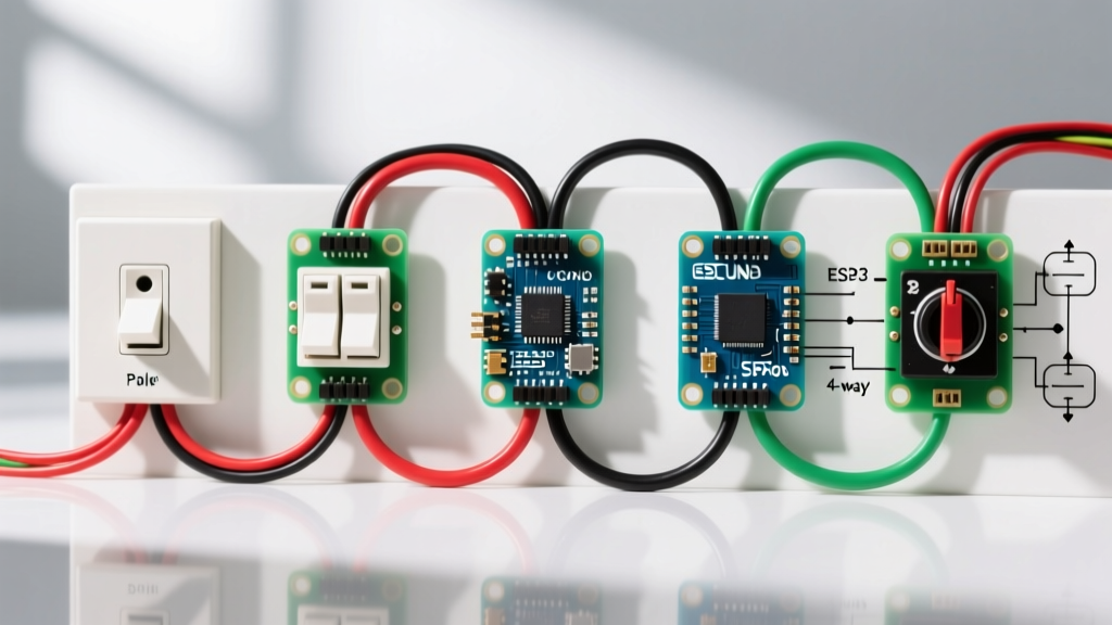
A 3-way setup allows control of a single load from two locations. The electrical switch wiring diagram for this scenario depicts two Single-Pole Double-Throw (SPDT) switches. The critical feature here is the 'Common' terminal and the two 'Traveler' terminals.
Decoding the Terminals
On a physical switch like the Leviton 5603-2W, the Common terminal is typically a darker brass or black screw, while the Traveler terminals are lighter brass.
- Switch 1 (Power Source): The incoming Line (hot) connects to the Common (dark) screw. The two Traveler wires (usually red and black from a 14/3 or 12/3 Romex) connect to the light brass screws.
- Switch 2 (Load Side): The Load wire (heading to the fixture) connects to the Common (dark) screw. The two Traveler wires from the 3-wire cable connect to the light brass screws.
Edge Case: Ghost Switching
A common failure mode in 3-way diagrams is misidentifying the Common terminal. If a traveler is placed on the common screw, the circuit will exhibit 'ghost switching'—where one switch must remain in a specific position for the other switch to function. Always verify the common terminal with a non-contact voltage tester before disconnecting an old switch.
Scenario 3: 4-Way Switch Integration (The Intermediate)
When a load must be controlled from three or more locations, a 4-way switch is inserted between two 3-way switches. The schematic shows a Double-Pole Double-Throw (DPDT) switch that simply crosses or passes through the traveler paths.
Wiring the 4-Way Intermediate
Using a standard 15A 4-way switch (e.g., Eaton 327W), you will find four brass traveler screws and one green ground screw. There is no 'Common' terminal on a 4-way switch.
- Line-In Travelers: The two traveler wires coming from the first 3-way switch connect to the top two brass terminals (or the two terminals of the same color on one side of the switch).
- Line-Out Travelers: The two traveler wires continuing to the second 3-way switch connect to the remaining two brass terminals.
Note: Never connect the Line or Load hot wires to a 4-way switch. It strictly handles traveler traffic. If you have a 4-wire cable entering the box, ensure the neutral and ground are properly routed and not confused for travelers.
Scenario 4: Smart Switch Wiring (The Neutral Requirement)
Modern smart switches, particularly those utilizing Wi-Fi, Zigbee, or the new 2026 Matter-over-Thread protocols, require constant standby power to maintain network connectivity. This fundamentally changes the electrical switch wiring diagram by introducing a Neutral Wire connection.
Anatomy of a Smart Switch Connection
Let's look at the Lutron Caseta PD-6ANS (a neutral-required model, typically retailing around $65 in 2026).
- Line (Hot): Incoming black wire.
- Load: Outgoing black wire to the fixture.
- Neutral: Must connect to the bundle of white wires in the back of the box. Warning: Do not use the ground wire as a neutral. This creates a severe shock hazard and will trip AFCI/GFCI breakers immediately.
- Ground: Bare copper to the green lead.
Box Fill Calculations for Smart Switches
Smart switches have significantly larger physical bodies than standard toggle switches. Under NEC Article 314.16, a standard switch counts as two conductor allowances for box fill. However, the physical bulk of a smart switch often requires a minimum of an 18-cubic-inch single-gang box (preferably a 22-cubic-inch 'deep' box) to accommodate the wire nuts and the device chassis without crushing the ROMEX insulation.
Scenario 5: Switch/Receptacle Combo (Half-Hot Outlet)
A combo device features a single-pole switch and a standard 15A duplex receptacle on a single yoke. The most common diagram for this device is the 'half-hot' scenario, where the switch controls a lamp plugged into the top half of the outlet, while the bottom half remains constantly powered.
The Critical Step: Breaking the Fin
On a device like the Leviton 5225-W, the hot (brass) side of the receptacle features a small metal connecting fin (or tab) between the top and bottom brass screws.
- Use a pair of needle-nose pliers (like the Klein 203-8) to bend and snap off the brass fin connecting the two hot terminals. Do not break the silver (neutral) fin.
- Connect the constant Line (hot) to the bottom brass screw.
- Connect the Switched Load wire to the top brass screw.
- Connect the incoming neutral to either silver screw (the neutral side remains bridged).
- Pigtail the ground wire to the green screw.
Comparison Matrix: Switch Types & Specifications
| Scenario | Switch Type | Terminals Required | Neutral Needed? | Avg 2026 Cost |
|---|---|---|---|---|
| Standard Single-Pole | SPST | 2 Brass, 1 Ground | No | $1.50 - $3.00 |
| 3-Way Configuration | SPDT | 1 Common, 2 Traveler, 1 Gnd | No | $3.50 - $6.00 |
| 4-Way Intermediate | DPDT | 4 Traveler, 1 Ground | No | $8.00 - $14.00 |
| Smart Switch (Wi-Fi/Thread) | SPST + Relay | Line, Load, Neutral, Ground | Yes (Usually) | $45.00 - $75.00 |
| Switch/Receptacle Combo | SPST + Duplex | 2 Hot, 2 Neutral, 1 Gnd | Yes (for receptacle) | $5.00 - $9.00 |
Code Compliance and Safety Standards
When executing any electrical switch wiring diagram, adherence to national safety standards is non-negotiable. The National Electrical Code (NEC) mandates strict grounding and box-fill rules to prevent thermal events. Furthermore, the Consumer Product Safety Commission (CPSC) heavily advises the use of AFCI (Arc-Fault Circuit Interrupter) protection in all residential living areas, which means your switch wiring must be free of loose connections that could trigger nuisance tripping.
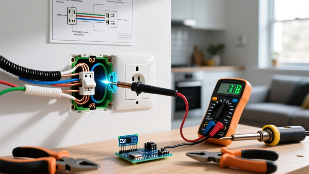
Always verify that your circuit is de-energized using a CAT III or CAT IV rated multimeter before touching any bare copper. For comprehensive workplace and residential electrical safety protocols, refer to the guidelines published by OSHA's Electrical Safety division. Remember, a diagram is merely a map; your safety relies on proper physical execution, correct tool usage, and strict adherence to local electrical codes.