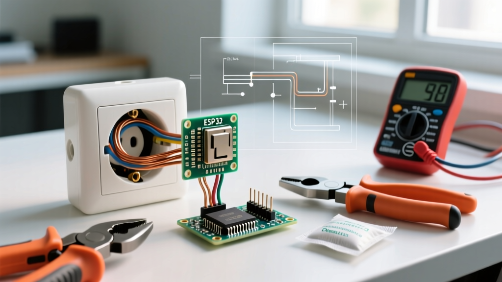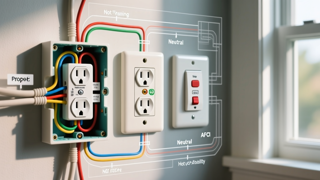

The Diagnostic Phase: Why Did Your Outlet Fail?
Before you grab a screwdriver and learn how to replace an electrical outlet, you must diagnose why the existing receptacle failed. Outlets rarely die without a reason; they are usually victims of thermal cycling, improper installation, or overloaded circuits. According to the National Fire Protection Association (NFPA), electrical failures and malfunctions are among the leading causes of residential fires, often originating at degraded receptacle terminations.
When a standard 15-amp duplex receptacle (like the ubiquitous Leviton 5366-W) is subjected to continuous high-draw loads—such as a 1500W space heater pulling 12.5 amps—the internal brass contacts heat up. If the wires were 'backstabbed' (pushed into the rear quick-wire holes) rather than wrapped around the terminal screws, the microscopic spring clips lose their temper over time. This creates a high-resistance connection, leading to arcing, voltage drop, and eventually, a melted faceplate.
Receptacle Failure Matrix
| Symptom | Visual / Tactile Clue | Root Cause Diagnosis | Required Action |
|---|---|---|---|
| Dead Outlet (No Power) | NCVT tester reads zero; breaker is ON. | Open neutral upstream or tripped GFCI. | Trace upstream devices; reset GFCI. |
| Warm Faceplate | Plastic feels hot to the touch under load. | Backstabbed connection arcing; loose terminal. | Replace outlet; side-wire with torque driver. |
| Buzzing / Hissing | Audible vibration near the yoke. | Severe arcing; imminent fire hazard. | Kill breaker immediately; replace and inspect wire insulation. |
| Plugs Fall Out | Receptacle slots offer zero mechanical grip. | Worn internal brass wipers from years of use. | Replace with Tamper-Resistant (TR) model. |
Essential Tools for 2026 Receptacle Replacement
Modern electrical codes and best practices demand precision. The days of guessing wire strip lengths and tightening screws by 'feel' are over. To properly troubleshoot and replace an outlet today, you need the following calibrated tools:
- Non-Contact Voltage Tester (NCVT): Klein Tools NCVT-3 (approx. $35). Verifies the circuit is dead before you touch bare copper.
- Digital Multimeter (DMM): Fluke 117 True-RMS (approx. $210). Essential for diagnosing phantom voltages, checking continuity, and verifying exact line voltage (typically 120V ±5%).
- Wire Strippers: Klein Tools 11055 (approx. $28). Specifically calibrated to strip 14 AWG and 12 AWG solid copper without nicking the conductor, which creates a fracture point.
- Torque Screwdriver: Wiha 61085 or Milwaukee 48-22-6101 (approx. $90-$120). The NEC strictly requires terminations to be tightened to the manufacturer's specified torque.
- Receptacle Tester: Gardner Bender GRT-501 (approx. $12). For quick post-installation polarity and ground verification.
Step-by-Step Guide: How to Replace an Electrical Outlet
Once you have diagnosed the fault and gathered your tools, follow this precise procedure to ensure a safe, code-compliant installation.
Step 1: Isolate and Verify
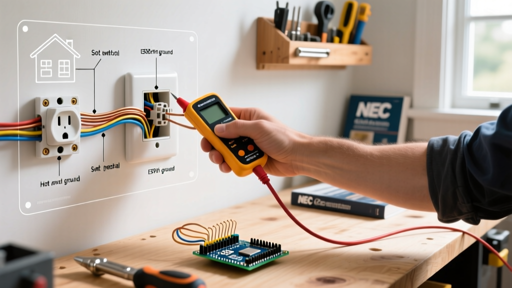
Locate your electrical panel and switch off the corresponding breaker. Do not rely solely on a wall switch to kill power to a receptacle. Insert your NCVT into the top and bottom slots of the dead outlet. Next, remove the faceplate and test the exposed terminal screws with a Fluke 117 multimeter (set to AC Voltage) between the brass (hot) screws and the bare copper ground wire. The reading must be 0.0V.
Step 2: Extract and Inspect the Wiring
Unscrew the top and bottom yoke screws and gently pull the receptacle out of the gang box. Stop and look. If the wire insulation is brittle, scorched, or melted back more than an inch, you must cut the damaged wire back to fresh, clean copper. If the box is packed with wires, carefully untangle them to identify the line (incoming power), load (downstream power), and neutral (white) conductors.
Step 3: Precision Wire Preparation
Using your Klein 11055 strippers, cut the ends of the wires to ensure they are perfectly straight. Strip exactly 5/8 of an inch of insulation from the end of the 14 AWG or 12 AWG solid copper wire. The NEC and manufacturers like Hubbell and Leviton specify 5/8' to ensure no bare copper is exposed outside the terminal block, and no insulation is trapped under the screw head, which would cause a high-resistance fault.
Step 4: Proper Termination (The Shepherd Hook)
Never use the backstab holes on standard residential receptacles. Instead, use the side-wire screw terminals. Form a 'shepherd hook' in the wire using needle-nose pliers. Loop the hook clockwise around the terminal screw. This ensures that as you tighten the screw (clockwise), the hook is pulled tighter around the shaft rather than being pushed out. Place your torque screwdriver, set to the manufacturer's specification (typically 12 in-lbs for standard 15A duplex receptacles), and tighten until the driver clicks.
NEC Code Note: The Consumer Product Safety Commission (CPSC) and the National Electrical Code (NEC) mandate that all 15A and 20A, 125V and 250V receptacles installed in residential dwellings must be listed as Tamper-Resistant (TR). Always ensure your replacement outlet features the 'TR' stamp on the yoke, which indicates internal shutters that prevent children from inserting foreign objects.
Advanced Troubleshooting: Edge Cases and Hidden Hazards
Sometimes, replacing an outlet reveals deeper wiring anomalies. As a DIYer or apprentice electrician, you must recognize these edge cases to prevent catastrophic failures.
The Multi-Wire Branch Circuit (MWBC) Trap
If you pull the old outlet out and see a red wire and a black wire connected to the two brass hot screws, you are dealing with a Multi-Wire Branch Circuit. This means two separate 120V circuits are sharing a single neutral (white) wire.
The Hazard: If you replace the outlet without breaking the brass connecting fin (the small metal tab between the two brass screws), you will create a dead short between the two hot legs (240V across a 120V device), resulting in an immediate, violent breaker trip and potential arc flash.
The Fix: You must use lineman's pliers to snap off the brass fin on the hot side of the new receptacle, leaving the silver (neutral) side intact. Furthermore, NEC code requires MWBCs to be protected by a two-pole breaker or a handle-tie to ensure both circuits are disconnected simultaneously during maintenance.
Bootleg Grounds and False Safety
When testing an old outlet, your plug-in tester might show 'Correct Wiring' (two yellow lights). However, if you open the box and find the green ground screw is jumpered to the white neutral wire, this is a 'bootleg ground.' This is an illegal and highly dangerous workaround used to trick testers. If a fault occurs, the neutral wire will carry 120V to the chassis of whatever appliance you plug in, creating a severe shock hazard. You must remove the jumper and either run a new ground wire back to the panel or replace the receptacle with a GFCI (Ground Fault Circuit Interrupter), labeled 'No Equipment Ground,' as permitted by the NFPA 70 (National Electrical Code).
Final Testing and Reassembly
Once the wires are terminated and torqued, carefully fold the wires back into the gang box. Use a 'Z-fold' technique: push the bare ground wires deep into the back of the box, fold the white neutrals into the middle, and tuck the hot wires neatly behind the receptacle yoke. Secure the outlet to the box using the included 6-32 mounting screws, ensuring the yoke sits flush against the drywall or plaster.
Restore power at the breaker panel. Use your Gardner Bender receptacle tester to verify correct polarity and grounding. Finally, use your Fluke 117 to measure the voltage at the face of the outlet; a healthy circuit should read between 114V and 126V. By combining rigorous diagnostic troubleshooting with precision installation techniques, you ensure your home's electrical infrastructure remains safe, reliable, and fully compliant with modern standards.