
Why Install an Outside Electric Outlet?
Adding an outside electric outlet to your home's exterior is one of the most practical DIY electrical upgrades you can undertake. Whether you are plugging in holiday lighting, powering an electric vehicle (EV) charger, running a pressure washer, or setting up an outdoor entertainment system, having a dedicated, code-compliant exterior receptacle eliminates the severe fire and tripping hazards associated with running extension cords through windows or doors. According to the U.S. Consumer Product Safety Commission (CPSC), extension cords are responsible for approximately 3,300 home fires annually, many of which stem from outdoor misuse and weather exposure.
This beginner installation tutorial will walk you through extending an existing indoor circuit to the exterior of your home. We will focus on compliance with the latest National Electrical Code (NEC) standards, which mandate Ground Fault Circuit Interrupter (GFCI) protection and specific weatherproof enclosures for all outdoor receptacles.
CRITICAL SAFETY WARNING: Working with electricity carries the risk of fatal shock or fire. Always shut off the main breaker for the circuit you are working on and verify it is dead using a non-contact voltage tester. If your home's wiring is outdated (e.g., knob-and-tube or ungrounded aluminum), consult a licensed electrician.
Project Overview and 2026 Cost Breakdown
Before purchasing materials, it is essential to understand the financial scope of the project. Material costs have stabilized in 2026, but premium weatherproof components remain a necessary investment. Below is a realistic cost breakdown for a standard exterior outlet installation extending from an adjacent interior wall.
| Item | Specific Model / Type | Estimated Cost (2026) |
|---|---|---|
| GFCI Receptacle | Leviton 15A Decora (R92-GFNT1) | $22.00 - $26.00 |
| Weatherproof Cover | TayMac MM410W Extra-Duty In-Use | $18.00 - $24.00 |
| Outdoor Cable | Southwire 12/2 UF-B (per foot) | $1.25 - $1.75 / ft |
| Exterior Box | Raco 5320-0 1-Gang Die-Cast | $8.00 - $12.00 |
| Miscellaneous | Cable clamps, wire nuts, silicone | $10.00 - $15.00 |
| Total Estimated Cost | Excluding specialized tools | $75.00 - $125.00 |
Required Tools and Specific Materials
To ensure a professional, long-lasting installation, gather the following tools and materials. Do not substitute interior-rated NM-B (Romex) cable for outdoor use; moisture will destroy the paper wrapping and cause a short circuit.
- Non-Contact Voltage Tester: Klein Tools NCVT-2 (essential for verifying dead circuits).
- Wire Strippers: Capable of stripping 12 AWG and 14 AWG solid copper.
- Drill and Bits: Hammer drill with a 3/4-inch masonry bit (for brick/stucco) or a 3/4-inch spade bit (for wood siding).
- UF-B Cable: 12/2 Underground Feeder cable (rated for direct burial and wet locations).
- Silicone Caulk: 100% exterior-grade waterproof silicone for sealing the wall penetration.
- Wire Connectors: Ideal Wing-Nut connectors (rated for 12 AWG solid wire).
Step-by-Step Installation Guide
Step 1: Power Isolation and Verification
Locate your main electrical panel and identify the breaker controlling the interior outlet you plan to tap into. Switch the breaker to the OFF position. Plug a lamp or voltage tester into the interior outlet to confirm power is cut. Next, remove the interior outlet's faceplate and test the bare wires with your non-contact voltage tester. The National Fire Protection Association (NFPA) strongly emphasizes double-verification of dead circuits before any physical contact with conductors.
Step 2: Routing the UF-B Cable
Determine the path for your 12/2 UF-B cable. If drilling through a wood-framed exterior wall, use a 3/4-inch spade bit. If drilling through masonry or stucco, use a hammer drill with a masonry bit. Drill from the inside out to prevent blowing out the exterior siding. Feed the UF-B cable through the hole, leaving at least 8 inches of slack inside the interior wall box and 10 inches protruding outside. Seal the interior and exterior gaps around the cable generously with 100% silicone caulk to prevent moisture and pest intrusion.
Step 3: Mounting the Weatherproof Box
Attach the die-cast exterior receptacle box to the wall. If mounting to wood siding, use exterior-grade stainless steel screws. If mounting to masonry, insert plastic anchors before driving the screws. Pro-Tip: Apply a bead of silicone caulk behind the top and side edges of the box before mounting, but leave the bottom edge uncaulked. This creates a 'weep hole' that allows any internal condensation to drain out rather than pooling inside the enclosure.
Step 4: Wiring the GFCI Receptacle
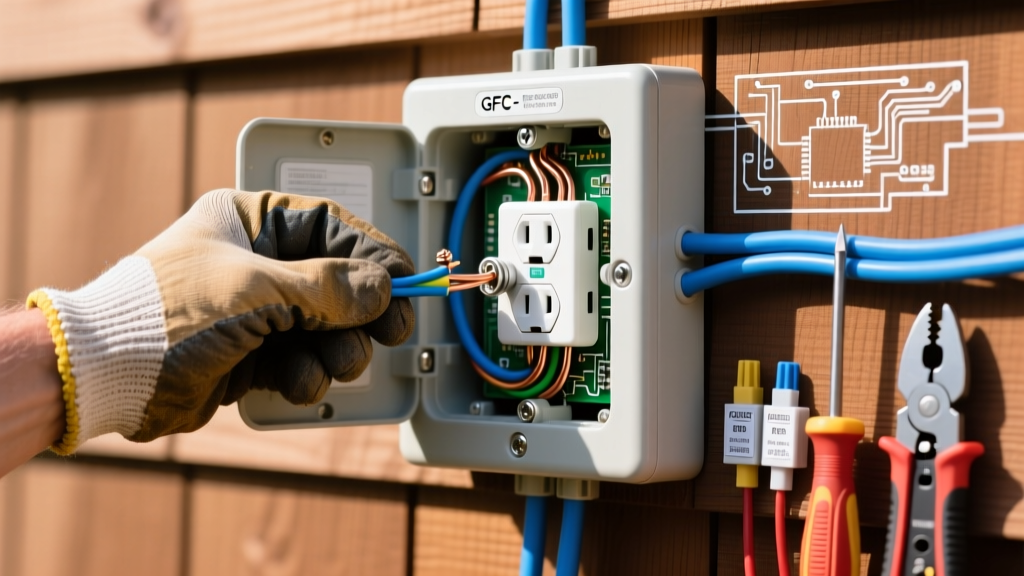
This is the most critical step. A GFCI receptacle has two sets of terminals: LINE (incoming power) and LOAD (downstream protection). For a single outside electric outlet, you will only use the LINE terminals.
- Strip 3/4 inch of insulation from the black (hot), white (neutral), and bare copper (ground) wires of the UF-B cable.
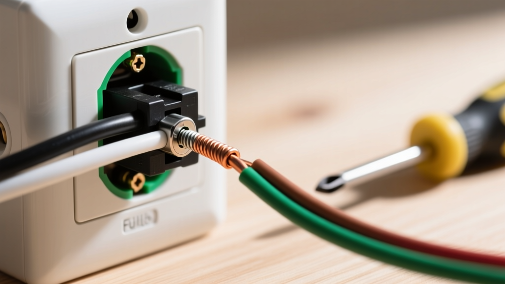
- Connect the bare copper ground wire to the green grounding screw on the GFCI. Loop it clockwise so the screw pulls the wire tight as you tighten it.
- Connect the white neutral wire to the silver LINE terminal screw (again, looping clockwise).
- Connect the black hot wire to the brass LINE terminal screw.
- Carefully fold the wires into the back of the exterior box, ensuring no bare copper is touching the metal box or other terminals. Secure the GFCI to the box using the provided mounting screws.
Step 5: Sealing and Final Testing
Attach the extra-duty 'in-use' weatherproof cover. These covers are designed with a deep bubble that allows a cord to be plugged in while keeping the lid completely closed. Secure the cover to the box, ensuring the rubber gasket is seated evenly. Return to your electrical panel and flip the breaker back to the ON position. Press the 'TEST' button on the GFCI; it should click and cut power. Press 'RESET' to restore power. Plug in a lamp or tool to verify functionality.
Common Failure Modes and Troubleshooting
Even careful beginners can encounter issues. Here is how to diagnose the most common problems when installing an outside electric outlet:
- GFCI Trips Immediately Upon Reset: This usually indicates a ground fault or a reversed Line/Load wiring configuration. Double-check that your incoming power is on the LINE terminals, not LOAD. Also, ensure no bare ground wire is accidentally touching the silver or brass terminal screws.
- Breaker Trips at the Main Panel: You likely have a dead short. This happens if the black and white wires are touching, or if a wire nut is loose inside the interior junction box. Turn the power back off and inspect all splices.
- Moisture Inside the Cover: If you see condensation inside the bubble cover, your weep hole (the uncaulked bottom edge of the box) is blocked, or the rubber gasket on the cover is pinched. Re-seat the gasket and clear the bottom edge of the box.
Frequently Asked Questions
Can I use standard NM-B (Romex) cable outdoors if it is inside a conduit?
No. Standard NM-B cable is not rated for wet locations, and conduit outdoors is considered a wet location due to condensation and temperature fluctuations. You must use UF-B cable or individual THWN-2 wires pulled through the conduit.
Do I need a permit to install an outside electric outlet?
In most municipalities, adding a new exterior receptacle requires a minor electrical permit and a subsequent inspection. This ensures your GFCI protection and weatherproofing meet local codes. Check with your local building department before starting.
Can I daisy-chain multiple outdoor outlets from this GFCI?
Yes. By wiring subsequent outdoor receptacles to the LOAD terminals of this primary GFCI, you can protect multiple downstream outlets without buying additional expensive GFCI receptacles. Ensure your circuit breaker has the amperage capacity to handle the additional load.