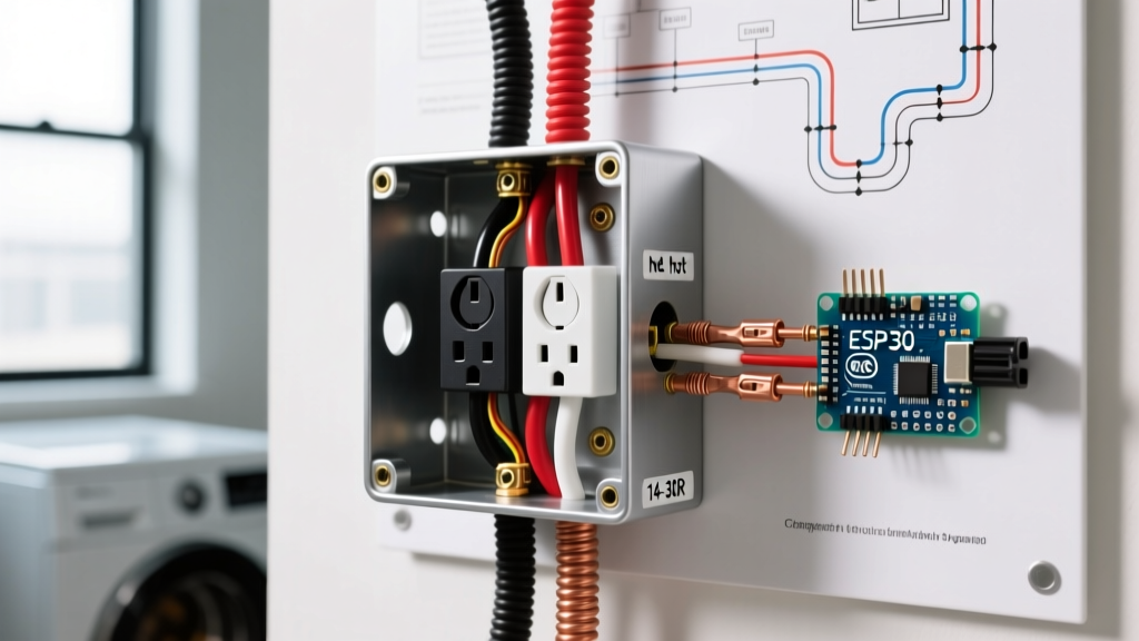

The Critical Role of the Electricity Outlet Cover
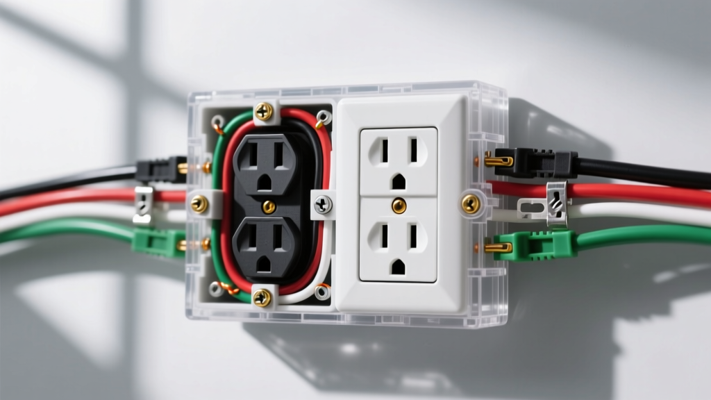
Replacing or upgrading an electricity outlet cover (technically known as a faceplate or receptacle wall plate) is a fundamental electrical maintenance task that bridges safety, code compliance, and aesthetic finishing. While often treated as an afterthought, the faceplate serves as the primary physical barrier preventing accidental contact with energized 120V/240V terminals and grounding dust or moisture ingress into the wall cavity. According to the National Fire Protection Association (NFPA), improper or missing faceplates contribute to thousands of residential electrical shocks and arc flash incidents annually.
This comprehensive guide details the exact procedures for installing standard indoor covers, GFCI-specific plates, and NEMA 3R-rated weatherproof "in-use" covers for outdoor applications, integrating 2026 material standards and National Electrical Code (NEC) requirements.
Material Science: Nylon vs. Polycarbonate vs. Thermoset
Before beginning installation, selecting the correct material for your specific environment is critical. Cheap covers crack under torque or degrade under UV exposure.
- Thermoset (Bakelite): The legacy standard. Highly rigid and flame-resistant, but extremely brittle. Prone to hairline cracking if the electrical box is slightly misaligned.
- Nylon (e.g., Leviton 80401): The modern residential standard. Offers excellent flexibility, impact resistance, and can bend slightly to accommodate uneven drywall without snapping. Typically priced around $1.20 to $1.80 per plate.
- Polycarbonate: Used for mid-size and jumbo plates. Highly durable and resistant to UV degradation, making it ideal for sunrooms or semi-exposed patios.
- Die-Cast Aluminum/Zinc: Mandatory for heavy-duty commercial or industrial outdoor applications. Often integrated into weatherproof in-use enclosures (e.g., Taymac MX850W).
Required Tools and 2026 Material Costs
Precision tools prevent stripped screws and cracked nylon. Avoid using motorized drills for faceplate installation; the high RPM easily strips the soft brass 6-32 UNC threads on the receptacle yoke.
| Tool / Material | Specification / Model | Est. Cost (2026) | Purpose |
|---|---|---|---|
| Voltage Tester | Klein Tools NCVT-3 (Dual Range) | $28.00 | Verifying de-energized state (12-1000V AC) |
| Screwdriver | Knipex 1162 Phillips #2 | $14.50 | Perfect bit fitment to prevent cam-out on 6-32 screws |
| Box Extender | Arlington BE1 (Non-Combustible) | $3.50 | Bringing recessed boxes flush to NEC 314.20 standards |
| Outdoor Cover | Taymac MX850W In-Use | $16.00 | Weatherproof enclosure for damp/wet locations |
| Sealant | GE Advanced Silicone 2 (Clear) | $8.50 | Waterproofing perimeter of outdoor plates |
Phase 1: De-energization and Box Preparation
Safety Warning: Never assume a circuit is dead based on the wall switch position. Receptacles are often on different circuits than overhead lighting. Always verify at the terminal.
- Isolate the Circuit: Turn off the corresponding breaker in the main service panel. If the panel is unlabeled, turn off the main breaker to guarantee safety.
- Verify Zero Energy: Insert the Klein NCVT-3 into the top and bottom slots of the receptacle. The tool must remain completely dark and silent. Test the tool on a known live circuit afterward to confirm the battery and sensor are functional.
- Remove Existing Cover: Use the Knipex #2 Phillips to remove the center 6-32 brass screw. Retain the screw; manufacturer-provided screws on new covers are often lower quality than OEM brass.
- Inspect Box Alignment: Check the gap between the electrical box edge and the finished wall surface. Per NEC Article 314.20, in combustible walls (drywall/wood), the box must be flush. In non-combustible walls (masonry/plaster), it may be recessed up to 1/4 inch. If the gap exceeds this, install an Arlington BE1 box extender ring before mounting the new cover.
Phase 2: Standard Indoor Electricity Outlet Cover Installation
Installing a standard indoor faceplate requires attention to torque and alignment to prevent aesthetic flaws and structural failure.
- Clean the Receptacle Yoke: Wipe the plaster ears (the metal tabs that rest against the drywall) with a dry cloth. Paint buildup or drywall compound here will cause the cover to sit crooked.
- Align the Faceplate: Slide the new nylon or polycarbonate cover over the receptacle. Ensure the top and bottom edges are perfectly parallel to the floor. Use a 2-inch torpedo level if necessary.
- Thread the Screw by Hand: Insert the 6-32 brass screw through the center hole. Critical Step: Thread it entirely by hand for the first 3-4 turns. If you use a screwdriver immediately, you risk cross-threading the soft brass yoke, which permanently ruins the receptacle.
- Final Torque: Tighten the screw with the Phillips screwdriver until the cover is snug against the wall. Stop turning the moment you feel resistance. Over-tightening to >0.5 Nm will warp nylon plates, causing a visible "dimple" around the screw head, or snap thermoset plates entirely.
Special Consideration: GFCI Receptacles
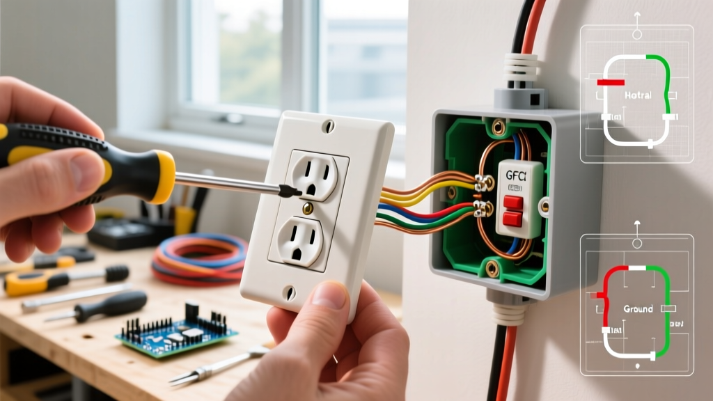
Ground Fault Circuit Interrupter (GFCI) outlets feature a wider rectangular test/reset button array. A standard duplex cover will not fit. You must use a GFCI-specific faceplate (e.g., Leviton 80405 or the plate included with the Leviton GFNT1). The installation steps are identical, but the tolerance for alignment is much tighter due to the larger rectangular cutout.
Phase 3: Outdoor Weatherproof "In-Use" Cover Installation
Outdoor installations are governed by NEC Article 406.9(B), which mandates that receptacles in wet locations must be enclosed in a weatherproof enclosure that provides protection even when a cord is plugged in (commonly called an "in-use" or "bubble" cover).
- Remove the Existing Standard Cover: Outdoor receptacles should already have a weatherproof box (e.g., Red Dot / Hubbell die-cast aluminum). Remove the old flat bubble cover.
- Prepare the Gasket: The Taymac MX850W and similar 2026 models include a closed-cell foam gasket. Ensure the gasket is seated perfectly in the channel on the back of the new enclosure. Do not use silicone between the gasket and the box; the compression of the foam is sufficient and allows for future removal.
- Route the Cord Channel: These covers feature a hinged flap with a notch at the bottom for extension cords. Ensure the notch aligns with the bottom of the receptacle orientation.
- Secure the Enclosure: Drive the provided stainless steel or brass screws through the cover's mounting holes into the weatherproof box's threaded hubs. Tighten firmly to compress the foam gasket evenly.
- Apply Perimeter Sealant: Using GE Advanced Silicone 2, apply a continuous, 1/8-inch bead along the top and side edges where the cover meets the siding, stucco, or brick. Do not caulk the bottom edge. Leaving the bottom uncaulked allows any incidental condensation or driven rain that bypasses the gasket to weep out, preventing trapped moisture and mold growth inside the wall cavity.
Troubleshooting Matrix: Common Installation Failures
| Failure Mode | Root Cause | Corrective Action |
|---|---|---|
| Cover sits crooked / tilted | Receptacle yoke is loose behind the drywall, allowing the outlet to rotate when the screw is tightened. | Loosen the top and bottom mounting screws on the receptacle itself, level the outlet, tighten the yoke screws, then re-install the faceplate screw. |
| Visible gap at top/bottom | Drywall is uneven, or the electrical box is recessed too far into the wall cavity. | Install an Arlington BE1 box extender, or use a "jumbo" / "mid-size" faceplate (e.g., Leviton 80401-M) which adds 3/16" to the width and height to bridge gaps. |
| Screw spins endlessly | Cross-threaded or stripped 6-32 brass hole on the receptacle yoke. | Replace the receptacle. There is no safe or code-compliant way to re-tap a stripped yoke thread on a 15A/20A residential device. |
| Outdoor cover fogging inside | Trapped humidity and lack of weep path; bottom edge was caulked. | Remove bottom caulk. Ensure the foam gasket is not pinched. Verify the weep hole at the bottom of the weatherproof box is clear of debris. |
NEC Code Compliance and Safety References
Adhering to the National Electrical Code is not just about passing inspections; it is about preventing arc faults and electrical fires. As highlighted by the U.S. Consumer Product Safety Commission (CPSC), exposed terminals due to missing or ill-fitting faceplates are a leading cause of pediatric electrical shocks and residential ignition events.
Furthermore, the U.S. Department of Energy notes that properly sealed outdoor enclosures prevent moisture-induced corrosion on the copper-to-brass terminal connections, which increases resistance, generates excess heat, and degrades the circuit's efficiency over time. Always ensure your electricity outlet cover matches the environment's NEMA rating and that all internal wiring remains fully enclosed within the approved junction box volume.
By following these precise material selections, torque specifications, and sealing methodologies, you ensure a safe, durable, and code-compliant installation that will withstand environmental and mechanical stress for decades.