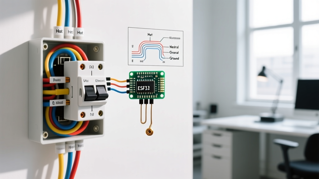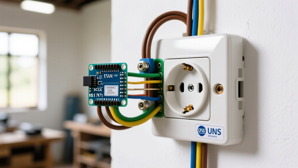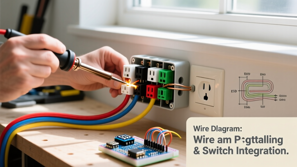

Why Extend an Electrical Outlet?
Extending an electrical outlet is a fundamental DIY electrical task required when adding a new workstation, installing a wall-mounted television, or upgrading a kitchen backsplash. While the concept of routing power from an existing receptacle to a new location seems straightforward, the execution requires strict adherence to the National Electrical Code (NEC) to prevent overheating, voltage drop, and arc faults. In 2026, with the widespread adoption of high-draw smart home appliances and EV chargers, ensuring your extended circuits can handle the load is more critical than ever.
This comprehensive guide walks you through the professional, step-by-step process of extending a 15-amp or 20-amp 120V receptacle circuit. We will cover box fill calculations, the mandatory pigtailing technique, and precise torque specifications that separate amateur hacks from safe, code-compliant installations.
Pre-Installation Checklist & Specialized Tools
Before cutting into any drywall or stripping wire, gather the correct materials. Using undersized wire or improper connectors is a leading cause of residential electrical fires. According to the U.S. Consumer Product Safety Commission (CPSC), improper wiring and overloaded circuits cause tens of thousands of house fires annually.
- Voltage Tester: Fluke 1AC-II VoltAlert (Non-contact) and a Klein Tools MM400 Multimeter for definitive zero-energy verification.
- Wire Strippers: Klein Tools 11063W (for 10-22 AWG solid/stranded wire) to ensure clean copper scoring without nicking the conductor.
- Connectors: Wago 221-413 Lever Nuts. These UL-listed push-wire connectors eliminate the under-tightening failure mode common with traditional twist-on wire nuts and accommodate 12-24 AWG wire.
- Cable: Southwire Romex SIMpull NM-B. Use 14/2 for 15A circuits and 12/2 for 20A circuits. Never extend a 20A circuit with 14 AWG wire.
- Torque Screwdriver: Klein Tools 69050. NEC 110.14(D) requires terminals to be tightened to the manufacturer's specified torque.
Understanding NEC Box Fill Capacity
The most common code violation when extending an electrical outlet is overcrowding the existing junction box. NEC Article 314.16 dictates strict volume allowances for every wire, clamp, and device inside a box. If you add a new 14/2 or 12/2 cable to an existing single-gang box, you are adding significant volume. If the box is overfilled, heat cannot dissipate, leading to insulation meltdown.
| Component Type | 14 AWG Wire (15A Circuit) | 12 AWG Wire (20A Circuit) |
|---|---|---|
| Each Hot/Neutral Conductor | 2.0 cubic inches | 2.25 cubic inches |
| All Ground Wires (Combined) | 1.0 cubic inch | 1.125 cubic inches |
| Internal Cable Clamps | 1.0 cubic inch | 1.125 cubic inches |
| The Receptacle Device | 4.0 cubic inches (2x vol) | 4.5 cubic inches (2x vol) |
Pro Tip: A standard single-gang 'old work' drywall box typically holds 14 to 18 cubic inches. If your math exceeds this, you must install a deeper box or use an extender ring before proceeding.
The Step-by-Step Installation Process
Step 1: Panel Lockout and Voltage Verification
Safety is non-negotiable. Turn off the circuit breaker supplying the outlet. Follow OSHA's Lockout/Tagout (LOTO) guidelines by placing a physical lock or heavy tape over the breaker and keeping the key on your person. Test the existing outlet with a non-contact voltage tester, then remove the faceplate and test the side terminals with a multimeter (Hot to Neutral, Hot to Ground) to confirm 0.0V.
Step 2: Assessing and Preparing the Existing Box
Remove the existing receptacle by unscrewing the top and bottom mounting tabs. Pull the device out gently. Calculate your box fill using the table above. If you have adequate space, proceed. If the box is packed tight, you will need to upgrade to a deep single-gang box (e.g., Carlon B618R-UPC, which offers 22 cubic inches of space).
Step 3: Routing and Stripping the New NM-B Cable
Run your new 14/2 or 12/2 Romex from the existing box to the new location. Secure the cable within 8 inches of the box using a Romex staple. Strip off exactly 3/4 inch of the outer PVC jacket where the cable enters the box, exposing the individual conductors. Strip 5/8 inch of insulation from the black (hot), white (neutral), and bare copper (ground) wires.
Step 4: The Pigtailing Technique (Critical Code Requirement)
Amateur electricians often 'daisy-chain' power by connecting the incoming power and the outgoing extended cable directly to the receptacle's side screws. This is a severe failure point; if the receptacle fails or is removed, the downstream outlet loses power, and the connection relies on the device's internal brass yoke, which can overheat.
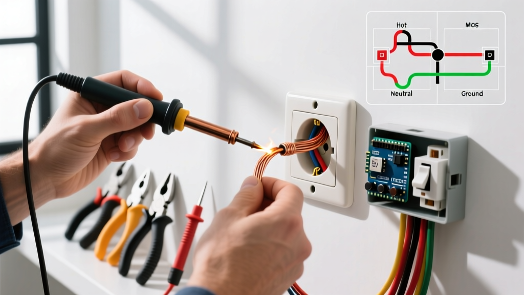
NEC Best Practice: Always use pigtails. Connect the incoming hot, the outgoing hot, and a 6-inch black pigtail together using a Wago 221-413 lever nut. Repeat for the neutral wires. Connect all ground wires together with a green wire nut or Wago, and attach a 6-inch bare copper pigtail to the green grounding screw on the receptacle.
NEC 300.14 requires at least 3 inches of free conductor to extend past the face of the box. Cutting 6-inch pigtails ensures you meet this code while providing enough slack to fold the wires neatly.
Step 5: Terminating and Torquing the Receptacle
Connect your black pigtail to the brass (hot) terminal and your white pigtail to the silver (neutral) terminal. Wrap the wire clockwise around the screw so that tightening the screw pulls the loop closed. Do not use the backstab push-in holes; they rely on weak internal spring clips that loosen over time due to thermal expansion and contraction.
Using your calibrated torque screwdriver, tighten the terminal screws to the manufacturer's specification, typically printed on the back of the receptacle. For most modern Leviton or Eaton 15A/20A receptacles, this is between 0.5 Nm and 1.2 Nm (approx. 14 in-lbs). Proper torque prevents arc faults and high-resistance connections.
Step 6: Folding, Mounting, and Testing
Carefully fold the wires into the box in a Z-pattern (grounds in the back, neutrals in the middle, hots in the front). Mount the receptacle, attach the faceplate, and restore power at the breaker. Test the new extended outlet with a Klein Tools RT250 GFCI Receptacle Tester to verify correct wiring, proper grounding, and GFCI functionality if applicable.
Common Failure Modes & Edge Cases
| Failure Mode | Symptom | Correction |
|---|---|---|
| Backstabbed Connections | Intermittent power loss when plugging in high-draw appliances; melted plastic smell. | Remove backstabbed wires immediately. Re-terminate using side-screw wiring or pigtails. |
| Over-torqued Terminals | Stripped brass/silver screws; cracked receptacle housing; deformed wire loops. | Replace the receptacle. Use a calibrated torque screwdriver to prevent mechanical stress. |
| Mixed Gauge Pigtails | 14 AWG pigtail used on a 12 AWG 20A circuit. The 15A pigtail can melt before the 20A breaker trips. | Ensure pigtail gauge exactly matches or exceeds the circuit's main wire gauge. |
Frequently Asked Questions
Can I extend an electrical outlet from a GFCI receptacle?
Yes, but you must decide if you want the new outlet to have GFCI protection. If you connect the new cable to the 'LOAD' terminals of the existing GFCI, the extended outlet will be protected. If you connect to the 'LINE' terminals (via pigtails), the new outlet will have standard protection only. Kitchens, bathrooms, and garages require GFCI protection per the latest NEC updates.
How many outlets can I put on a single 15-amp circuit?
The NEC does not specify a maximum number of receptacles on a general lighting and appliance branch circuit. However, standard electrical engineering practice and load calculations suggest a maximum of 10 to 12 receptacles on a 15A circuit to prevent nuisance tripping, assuming standard residential diversity factors. For dedicated appliance circuits, only one outlet should be installed.
Is it legal to use an extension cord inside a wall instead of Romex?
Absolutely not. NEC Article 400.8 explicitly forbids the use of flexible cords and cables (like extension cords) as a substitute for the fixed wiring of a structure, or for running through holes in walls, ceilings, or floors. You must use rated NM-B (Romex) or MC (Metal Clad) cable for in-wall extensions.
Final Thoughts on Code Compliance
Extending an electrical outlet is highly achievable for a meticulous DIYer, provided you respect the physics of electrical resistance and the legal requirements of the National Electrical Code (NFPA 70). By utilizing lever-nut connectors, calculating box fill volumes, and applying precise torque to your terminations, you ensure your home's electrical system remains safe, efficient, and fully compliant for decades to come.