
The Hidden Hazards of Improper Switch-Outlet Configurations
Combining a switched receptacle with a multi-location control setup is a staple of residential electrical design. When tackling electrical wiring 3 way switch outlet configurations—typically to control a half-hot duplex receptacle from two distinct locations, such as the top and bottom of a staircase—the margin for error is razor-thin. A miswired traveler, a broken neutral tab, or an omitted equipment grounding conductor can result in arcing faults, energized chassis, or catastrophic fire hazards.
As of the 2026 NEC cycle, inspectors are strictly enforcing neutral conductor mandates and tamper-resistant requirements that older DIY guides completely ignore. This comprehensive safety and code compliance guide breaks down the exact materials, National Electrical Code (NEC) articles, and termination procedures required to execute a 3-way switched outlet safely and legally.
Critical Safety Warning: Never rely solely on a wall switch to de-energize a circuit. Always perform Lockout/Tagout (LOTO) at the main service panel and verify zero energy state with a CAT IV rated voltage tester before exposing any conductors. For OSHA-compliant LOTO procedures, refer to the OSHA Control of Hazardous Energy guidelines.
Decoding the NEC: Code Requirements for Switch-Outlet Combos
To pass a municipal rough-in and final inspection, your 3-way switch and outlet wiring must adhere to several foundational NEC articles. Ignoring these is the primary reason DIY electrical work fails inspection and voids homeowner insurance policies.
1. The Neutral Conductor Mandate (NEC 404.2(C))
Historically, electricians ran a 2-wire cable (hot and switched-hot) from the power source to the first 3-way switch. The National Electrical Code (NFPA 70) now strictly requires a grounded neutral conductor to be present at every switch box. This ensures that future upgrades to smart switches, timers, or occupancy sensors—which require a neutral to power their internal logic boards—can be performed without tearing open drywall. You must run 12/3 or 14/3 NM-B cable from the panel to the first switch location to satisfy this code.
2. Tamper-Resistant Receptacles (NEC 406.12)
All 15A and 20A, 125V and 250V non-locking receptacles installed in dwelling units must be listed as Tamper-Resistant (TR). When selecting your outlet, look for the "TR" stamp on the face. The Leviton 5262-A (15A) or 5362-A (20A) are industry standards, costing approximately $3.50 to $4.25 each in 2026.
3. Multiwire Branch Circuit Handle Ties (NEC 210.4)
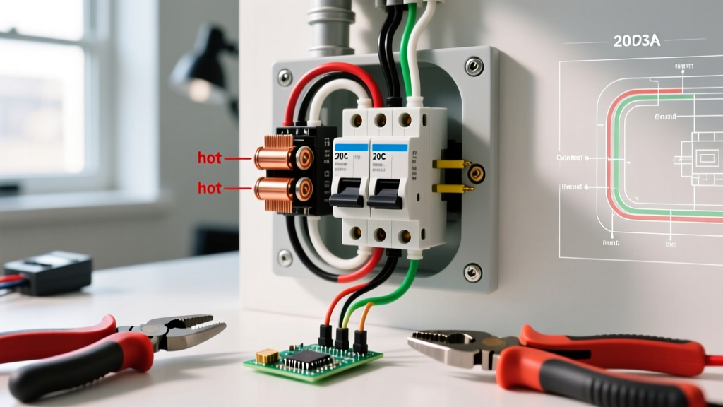
If your half-hot outlet is fed by a Multiwire Branch Circuit (MWBC)—where the top receptacle is on Phase A and the bottom is on Phase B—NEC 210.4(B) mandates a simultaneous disconnect. You must use a 2-pole breaker or approved handle ties on two adjacent single-pole breakers. Failure to do this creates a lethal shock hazard for anyone working on the receptacle, as turning off one breaker leaves the other half energized.
Material Sizing and Component Selection (2026 Standards)
Using undersized wire or劣质 (substandard) connectors is a leading cause of thermal runaway at termination points. Below is the required bill of materials for a standard 20-ampere 3-way switched receptacle circuit.
| Component | Specification / Model | Est. 2026 Cost | Code / Safety Purpose |
|---|---|---|---|
| Branch Circuit Wire | 12/3 NM-B w/ Ground (Southwire) | $0.85 / ft | Provides Hot, Neutral, Ground, and Travelers (NEC 404.2(C)) |
| 3-Way Switches (x2) | Leviton 5634 (20A, 120/277V) | $5.50 / ea | Heavy-duty commercial spec; side-wire only (no backstab) |
| Duplex Receptacle | Leviton 5362-A (20A TR) | $4.10 / ea | Tamper-resistant, allows tab-breaking for split wiring |
| Wire Connectors | Wago 221 Series (3-Port Lever) | $0.45 / ea | Visual inspection window, constant spring pressure (NEC 110.14) |
| Voltage Tester | Klein Tools NCVT-4IR | $45.00 | CAT IV rating + IR thermometer for post-energization thermal checks |
Execution: Wiring a 3-Way Switched Half-Hot Receptacle
This procedure assumes a standard topology: Power enters Switch Box 1, travels to Switch Box 2 via travelers, and the switched leg continues to the outlet box. The outlet box also receives a constant hot feed for the unswitched half of the receptacle.
Phase 1: Lockout, Tagout, and Verification
- Shut off the 20A breaker feeding the circuit at the main service panel.
- Apply a physical lockout hasp and tag to the breaker panel.
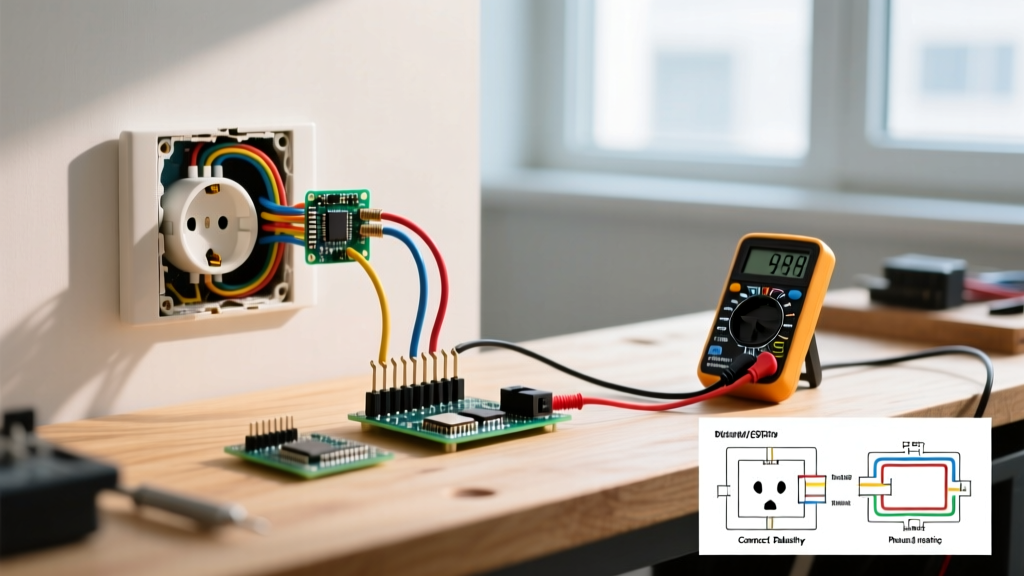
- Test the target receptacle and switches with a Klein NCVT-4IR, then verify with a contact solenoid tester or multimeter between hot and ground to confirm a zero-energy state.
Phase 2: Preparing the Receptacle (The Tab Break)
To create a half-hot (split-wired) outlet, you must isolate the two brass (hot) terminals while keeping the two silver (neutral) terminals bonded.
- Locate the Brass Tab: On the hot side of the Leviton 5362-A, locate the small metal fin connecting the top and bottom brass screws.
- Break the Tab: Use needle-nose pliers to grip the tab and bend it back and forth until it snaps cleanly. Warning: Do not snap the tab on the silver (white/neutral) side. Doing so will leave the bottom outlet without a neutral return path, creating an open neutral hazard.
Phase 3: Termination and Pigtailing
Modern code compliance heavily favors pigtailing over daisy-chaining, especially in switch boxes. Pigtailing ensures that if a device is removed for replacement, the downstream circuit is not interrupted.
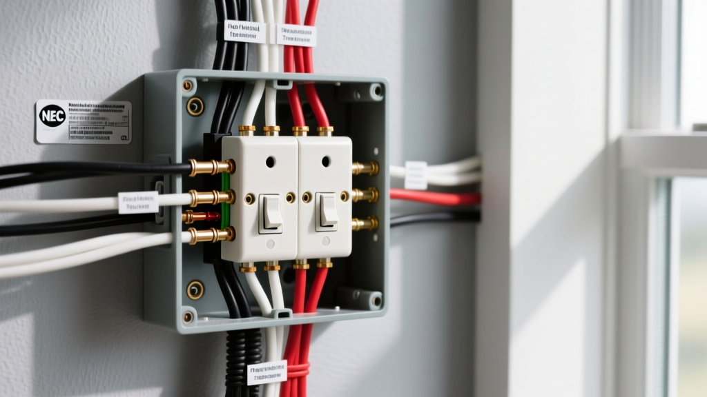
- Switch Box 1 (Line & Neutral Entry): Connect the incoming black (hot), white (neutral), and bare (ground) to the 12/3 NM-B heading to Switch Box 2. Use Wago 221 lever nuts. The white wire must be spliced through to provide the mandated neutral at the switch box.
- Switch Box 2 (Travelers & Switched Leg): The red and black wires from the 12/3 cable act as travelers, connecting to the brass traveler screws on the 3-way switch. The white neutral is capped with a Wago nut (satisfying NEC 404.2(C)). The black wire exiting to the outlet box becomes the switched hot, connected to the black common screw.
- Outlet Box Termination: Connect the constant hot to the bottom brass screw. Connect the switched hot (from the 3-way circuit) to the top brass screw. Connect the white neutral pigtail to the silver screw, and the bare copper to the green grounding screw.
Phase 4: Torque Verification
While often ignored in residential work, NEC 110.14(D) requires terminations to be torqued to the manufacturer's specifications. For Leviton 20A commercial spec-grade devices, the terminal screws should be tightened to approximately 12 to 14 inch-pounds. Using a calibrated torque screwdriver prevents stripped screws and ensures optimal surface contact, reducing long-term arcing risks.
Troubleshooting Matrix: Edge Cases & Failures
Even experienced DIYers encounter anomalies when dealing with 3-way switch loops. Use this matrix to diagnose issues before calling an inspector.
| Symptom | Root Cause | Code Violation? | Corrective Action |
|---|---|---|---|
| Breaker trips instantly when plugging in a lamp. | Neutral tab broken instead of hot tab; or hot/neutral reversed at receptacle. | Yes (Short Circuit) | Replace receptacle. Ensure only the brass fin is removed. Verify polarity. |
| Switches work, but GFCI breaker trips randomly. | Neutral and ground bonded downstream of the GFCI, or shared neutral on MWBC. | Yes (NEC 250.142) | Separate neutral and ground buses. Ensure the 3-way switch loop does not share a neutral with another circuit. |
| 3-way switches only work from one location. | Traveler wires swapped with the common wire on one of the 3-way switches. | No (Functional) | Identify the odd-colored screw (Common). Ensure the single line/load wire is on the common, and the two travelers are on the matching brass screws. |
| Receptacle face feels warm to the touch. | Backstabbed (push-in) terminations used instead of side-wire screw terminals. | Yes (Best Practice/UL) | Remove wires from push-in holes. Wrap wire clockwise around the side terminal screws and torque to 14 in-lbs. |
Final Inspection and Thermal Imaging
Once the devices are secured in the boxes and the faceplates are installed, remove the LOTO devices and re-energize the panel. According to the Consumer Product Safety Commission (CPSC), thermal anomalies are a primary indicator of impending electrical fires.
Plug a high-draw load (such as a 1500W space heater or heavy-duty work light) into the switched half of the outlet. Operate the 3-way switches several times under load. After 15 minutes, use the infrared thermometer function on your Klein NCVT-4IR to scan the switch and receptacle faceplates. The temperature should not exceed ambient room temperature by more than 10°F (5°C). If you detect a hot spot exceeding this threshold, de-energize immediately and inspect the termination points for loose strands, inadequate torque, or damaged insulation.
By adhering strictly to NEC 404.2(C), utilizing commercial-grade TR components, and enforcing proper torque specifications, your 3-way switch outlet installation will not only pass municipal inspection but will provide decades of safe, reliable operation.