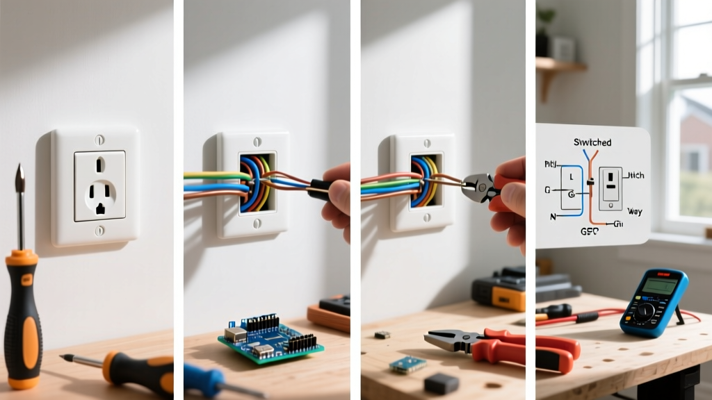

Mastering the Fundamentals: How to Install an Electrical Outlet Safely
Learning how to install an electrical outlet is a foundational skill for any DIYer or apprentice electrician. However, residential wiring is rarely one-size-fits-all. Depending on the room, the circuit layout, and the latest National Electrical Code (NEC) requirements, you will encounter vastly different wiring topologies. As of the 2023 NEC (widely enforced through 2026), requirements for Arc-Fault Circuit Interrupters (AFCI) and Ground-Fault Circuit Interrupters (GFCI) have expanded, making proper installation more critical than ever.
Before cutting any wires, always verify the circuit is dead using a non-contact voltage tester (like the Klein NCVT-3) and a multimeter. According to the Occupational Safety and Health Administration (OSHA), failure to verify zero energy is a leading cause of residential and commercial electrical accidents.
The Professional Toolkit: Beyond the Basics
To execute these scenarios flawlessly, you need more than a standard flathead screwdriver. Professional-grade installations require precision tools to prevent terminal damage and ensure long-term reliability.
- Wire Strippers: Klein Tools 11055 (Precision stripping for 10-18 AWG solid/stranded).
- Torque Screwdriver: Wiha 645P/T9 or similar, calibrated to inch-pounds (in-lbs).
- Receptacles: Leviton Pro Grade T52-A (15A) or Hubbell 5262 (20A). Avoid builder-grade $0.80 receptacles; Pro Grade models ($4.50–$6.00 each) feature deeper wire cups and thicker brass contacts.
- Wire Connectors: 3M Scotchlok or Ideal Wire-Nuts (specifically sized for the gauge combination).
Scenario 1: Standard End-of-Run 15A Receptacle
The end-of-run scenario is the most straightforward. You have a single 14/2 NM-B (Romex) cable entering the box, meaning this outlet is the final device on the circuit branch.
Step-by-Step Execution
- Prepare the Wires: Strip exactly 3/4-inch of insulation from the black (hot), white (neutral), and bare copper (ground) wires. Use the hole marked '14' or '12' on your strippers to avoid nicking the copper conductor, which creates a weak point prone to snapping under the screw head.
- Form the J-Hook: Use the looping hole on your strippers to create a smooth J-hook. The hook must wrap clockwise around the terminal screw. This ensures that tightening the screw pulls the wire loop tighter rather than pushing it outward.
- Terminate: Connect the bare ground to the green screw, the white neutral to the silver screw, and the black hot to the brass screw.
- Torque to Spec: Tighten the screws until your torque screwdriver clicks. For standard 15A/20A receptacles with #14 or #12 AWG solid copper wire, the manufacturer specification is almost universally 14 in-lbs.
Scenario 2: Middle-of-Run (Daisy Chain) Wiring
When an outlet is situated between the breaker panel and another downstream device, you will have two cables in the box: one incoming (line) and one outgoing (load). You have two methods to wire this: Pass-Through or Pigtailing.
| Method | Pros | Cons | Best Use Case |
|---|---|---|---|
| Pass-Through (Using both sets of terminal screws) |
Faster; uses no extra wire or wire nuts. | If the receptacle fails or is removed, downstream power is lost. Crowds the box. | Standard 15A living room or bedroom circuits with deep 22-cu-in boxes. |
| Pigtailing (Splicing wires with a jumper) |
Maintains downstream continuity if the receptacle fails. Neater box layout. | Requires extra wire, wire nuts, and more installation time. | Shallow boxes, multi-gang boxes, or critical circuits where continuity matters. |
Pro-Tip for Ground Pigtails: Never daisy-chain the ground wire through the green screw on the yoke. The NEC requires all grounding conductors to be spliced together with a pigtail to the device, ensuring the ground path remains intact even if the device is removed. Use a green wire nut or a crimp sleeve for this splice.
Scenario 3: Installing a 20A GFCI in Wet Locations
Kitchens, bathrooms, garages, and outdoor areas require Ground-Fault Circuit Interrupter (GFCI) protection per NEC Article 210.8. In modern construction, 20A circuits with 12/2 NM-B cable are standard for kitchen small-appliance branches.
Line vs. Load: The Critical Distinction
A GFCI receptacle (such as the Leviton GFSW1-KW) features two sets of terminals: LINE and LOAD.
- LINE Terminals: Connect the incoming power from the breaker panel here. The internal ground-fault sensor monitors current flowing through these terminals.
- LOAD Terminals: Connect outgoing cables here only if you intend to protect downstream standard receptacles. If you wire incoming power to the LOAD terminals by mistake, the GFCI will reset and appear to function, but it will offer zero ground-fault protection.
Code Alert: The National Fire Protection Association (NFPA) mandates that all 125-volt through 250-volt receptacles supplied by single-phase branch circuits rated 150 volts or less to ground, 50 amperes or less, in specific damp/wet locations must have GFCI protection. Always use a weather-resistant (WR) rated receptacle with an in-use bubble cover for outdoor installations.
Scenario 4: Split-Receptacle (Switched Half) for Living Rooms
In living rooms and bedrooms lacking overhead lighting, the NEC requires at least one receptacle to be controlled by a wall switch. This is achieved using a split-receptacle wired with a 3-wire cable (14/3 or 12/3).
Breaking the Fin
Standard duplex receptacles have a small metal tab (fin) connecting the top and bottom brass (hot) screws. To create a split outlet:
- Use needle-nose pliers to bend the brass fin back and forth until it snaps off completely. Do not break the silver (neutral) fin.
- Connect the black (always hot) wire from the 14/3 cable to the bottom brass screw.
- Connect the red (switched hot) wire from the 14/3 cable to the top brass screw.
- Connect the white neutral to the silver screw and the bare ground to the green screw.
This configuration leaves the bottom outlet always on for lamps or electronics, while the top outlet is controlled by the wall switch to power floor lamps.
Critical Torque Specifications & Failure Modes
Under-torquing or over-torquing terminal screws is a silent failure mode. According to the Consumer Product Safety Commission (CPSC), loose electrical connections generate excessive heat due to increased resistance, leading to arcing, melted insulation, and structural fires.
| Wire Gauge & Type | Target Torque (in-lbs) | Failure Mode if Incorrect |
|---|---|---|
| #14 AWG Solid Copper | 14 in-lbs | Thermal cycling loosens connection; arcing occurs. |
| #12 AWG Solid Copper | 14 in-lbs | Copper cold-flow deforms under high torque. |
| #10 AWG Stranded Copper | 30 in-lbs (Check Mfr) | Strands splay and break if over-torqued. |
The Danger of Backstabbing (Push-In Terminals)
Many builder-grade receptacles feature push-in (backstab) terminals on the rear. While the NEC permits their use for #14 AWG solid copper wire, professional electricians universally avoid them. Backstab terminals rely on a small internal spring-metal wedge to grip the wire. Over years of thermal expansion and contraction (from plugging in high-draw devices like space heaters or vacuum cleaners), this spring loses tension. The resulting micro-arcing generates intense localized heat, often melting the polycarbonate housing of the receptacle. Always use the side-binding screw terminals or the screw-to-clamp plates found on Pro Grade devices.
Final Inspection and Testing
Once the receptacle is secured to the box and the faceplate is installed, restore power at the breaker. Use a dedicated receptacle tester (like the Sperry ET6420) to verify correct wiring. The tester will confirm:
- Correct Polarity (Hot/Neutral not reversed)
- Equipment Grounding Conductor continuity
- GFCI trip functionality (if applicable)
By understanding these four common wiring scenarios and adhering to strict torque and termination standards, you ensure a safe, code-compliant installation that will last for decades.


