
Mastering the Art of the Receptacle Swap
Deciding to change an electrical outlet is one of the most common DIY electrical tasks, yet it remains a leading source of residential wiring errors. According to the National Fire Protection Association (NFPA), electrical distribution and lighting equipment are consistently among the top causes of home structure fires. Often, these fires trace back to high-resistance connections, loose terminals, or improper device replacements performed in previous decades.
While hiring a licensed electrician to swap a single receptacle typically costs between $150 and $250 in 2026, doing it yourself costs between $3 and $25 in parts. However, a simple 'one-size-fits-all' approach does not work. The wiring topology inside your wall box dictates the exact procedure. Below, we break down how to change an electrical outlet across four of the most common residential wiring scenarios, providing the exact technical specifications, torque values, and failure-mode preventions you need to do it right.
Scenario 1: The Standard 15A Duplex Replacement (Fixing Backstabbed Wiring)
The most frequent scenario involves replacing a worn-out 15-amp standard duplex receptacle. In homes built between the 1970s and early 2000s, electricians frequently used 'backstab' or push-in terminals to save time. Over years of thermal cycling (heating and cooling under load), these spring-loaded connections lose tension, leading to arcing, melted plastic, and intermittent power loss.
Step-by-Step Execution
- Verify De-energization: Turn off the breaker and test with a non-contact voltage tester (NCVT) like the Klein Tools NCVT1T, followed by a multimeter checking Hot-to-Neutral and Hot-to-Ground (both should read 0.0V).
- Extract Backstabbed Wires: Do not simply pull the wires out, which can strand and weaken the copper. Insert a small flathead screwdriver or an awl into the release slot next to the wire to disengage the internal spring catch.
- Strip and Prepare: Cut off the damaged, pitted ends of the wire. Using precision wire strippers (e.g., Klein 11055), strip exactly 3/4-inch of insulation. This is the standard gauge strip length marked on the back of almost all UL-listed 15A receptacles.
- Terminate on Side Screws: Form a J-hook in the wire and wrap it clockwise around the brass (hot) and silver (neutral) terminal screws. This ensures the screw tightens the loop rather than pushing it out.
- Apply Proper Torque: NEC Article 110.14(D) requires terminations to be torqued to the manufacturer's specifications. For most standard 15A receptacles (like the Leviton 5262-SW), this is 14 in-lbs. Use a calibrated torque screwdriver to prevent under-tightening (causing arcing) or over-tightening (stripping the screw head).
Scenario 2: The Split-Wired (Half-Switched) Receptacle
In many living rooms and bedrooms, you will encounter a split-wired receptacle. This setup features a wall switch that controls the top half of the outlet (usually for a lamp), while the bottom half remains constantly hot for electronics like TVs or routers. You can identify this by finding two different colored hot wires (typically one black and one red) attached to the brass screws.
The Critical Failure Mode: The Brass Fin
When you buy a new standard receptacle, the two brass hot screws are connected by a small metal break-off fin (tab). If you change an electrical outlet in a split-wired scenario and forget to break this tab, you will send 120V directly into the neutral return path of the switch loop the moment you turn on the breaker, resulting in a dead short and a tripped breaker.
Expert Tip: Before wiring the new device, use a pair of needle-nose pliers to grip the small brass tab on the hot side (the side with the shorter, darker screws) and bend it back and forth until it snaps off completely. Leave the silver (neutral) side tab intact.
Scenario 3: Upgrading to GFCI Protection
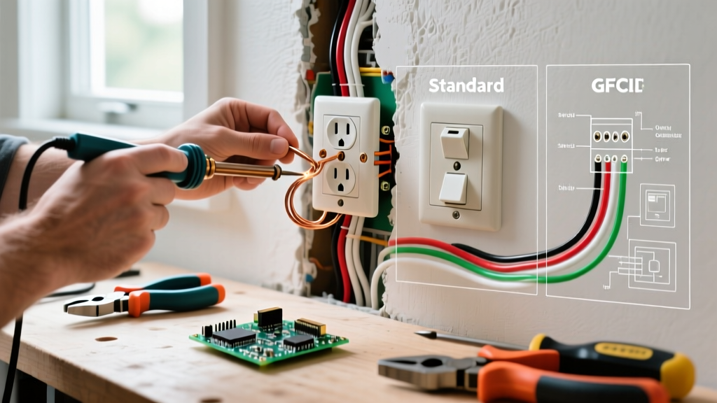
Upgrading a standard outlet in a kitchen, bathroom, garage, or exterior location to a Ground Fault Circuit Interrupter (GFCI) is a vital safety upgrade. The Electrical Safety Foundation International (ESFI) strongly advocates for GFCI protection in all areas where water and electricity may intersect, noting that GFCIs detect ground-fault imbalances as small as 4 to 6 milliamps and trip in as little as 20 to 30 milliseconds.
Navigating LINE vs. LOAD Terminals
Unlike standard receptacles, GFCI devices (such as the Leviton 8899-W 20A SmartLockPro) have two distinct sets of terminals: LINE and LOAD. Wiring these backward is the most common DIY error, resulting in an outlet that has power but provides zero ground-fault protection.
- LINE Terminals: These connect to the incoming power from the breaker panel. If you only have one set of wires (one black, one white, one bare copper) in the box, they always go to LINE.
- LOAD Terminals: These connect to downstream outlets, extending GFCI protection to the rest of the circuit. If you have two sets of wires in the box, you must identify the incoming power source using a multimeter before connecting the downstream wires to LOAD.
Procedural Check: Cap the LOAD wires temporarily with wire nuts. Turn the breaker on and use a multimeter to find which black wire carries 120V. That is your LINE wire. Turn the breaker back off, connect the LINE wires to the LINE terminals, connect the downstream wires to the LOAD terminals, and secure the bare copper wires to the green grounding screw and the metal box (if present) using a grounding pigtail.
Scenario 4: Upgrading from 15A to 20A Receptacles
Homeowners renovating kitchens or workshops often want to change an electrical outlet from a 15-amp model to a 20-amp model (identified by the T-shaped neutral slot) to accommodate high-draw appliances like commercial mixers or heavy-duty power tools. However, you cannot simply swap the device without verifying the circuit's physical constraints.
Wire Gauge and Breaker Verification
According to U.S. Consumer Product Safety Commission (CPSC) guidelines and NEC Article 210.21(B)(1), a 20-amp receptacle can only be installed on a 20-amp circuit wired with a minimum of 12 AWG copper wire.
If you open the wall box and find 14 AWG wire (which is noticeably thinner and usually has white or yellow Romex sheathing, compared to the thicker 12 AWG with yellow or orange sheathing), you must not install a 20A receptacle or upgrade the breaker to 20A. Doing so creates a severe fire hazard, as the 14 AWG wire will overheat and melt before the 20A breaker trips. If you have 14 AWG wire, you are restricted to a 15A breaker and 15A receptacles, regardless of the appliance plug shape (though 20A plugs physically will not fit into 15A slots, requiring an appliance cord change or a dedicated circuit pull).
Scenario Comparison & Cost Matrix
| Wiring Scenario | Recommended Device (2026) | Wire Gauge Required | Avg. DIY Cost | Estimated Time |
|---|---|---|---|---|
| Standard 15A Swap | Leviton 5262-SW (15A Duplex) | 14 AWG or 12 AWG | $3.50 - $5.00 | 15 - 20 mins |
| Split-Wired (Switched) | Leviton 5262-SW (Break brass tab) | 14 AWG or 12 AWG | $3.50 - $5.00 | 20 - 25 mins |
| GFCI Upgrade | Leviton 8899-W (20A GFCI) | 12 AWG (for 20A circuit) | $18.00 - $24.00 | 30 - 45 mins |
| 20A Heavy-Duty Upgrade | Leviton 5362-W (20A Duplex) | 12 AWG strictly required | $6.00 - $9.00 | 15 - 20 mins |
Final Troubleshooting & Safety Checklist
Once you have completed the physical installation and secured the receptacle to the junction box using the provided 6-32 machine screws, follow this final checklist before applying drywall compound or paint:
- Box Make-Up: Ensure no bare copper ground wire is touching the brass hot terminal screws. This is a common cause of immediate breaker trips.
- Receptacle Grade: For high-traffic areas or commercial applications, consider upgrading to 'Spec Grade' or 'Hospital Grade' receptacles. These feature thicker internal brass contacts and heavier steel mounting straps that resist warping when the device is screwed tightly into an uneven wall box.
- Testing: After restoring power at the panel, use a dedicated receptacle tester (like the Gardner Bender GFI-6302) to verify correct wiring. For GFCI outlets, press the 'TEST' button on the device itself to ensure the internal solenoid trips and cuts power, then press 'RESET'.
Understanding the specific wiring scenario inside your wall box transforms a potentially hazardous guesswork session into a precise, code-compliant upgrade. By respecting torque specifications, identifying line/load topologies, and verifying wire gauges, you ensure your home's electrical infrastructure remains safe and reliable for decades to come.