
Understanding the Switched Electrical Outlet
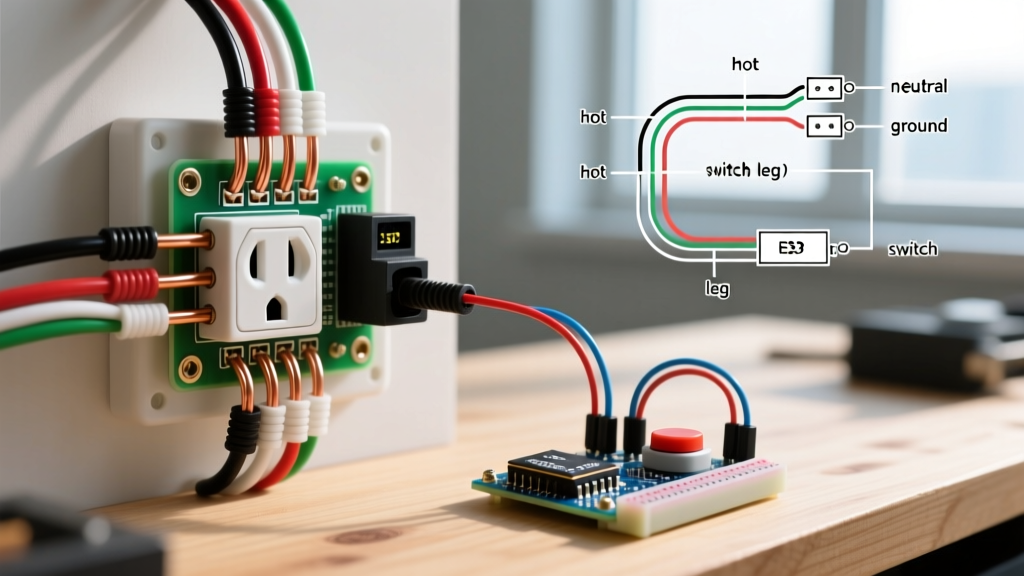
A switched electrical outlet is a fundamental wiring configuration used primarily in living rooms, bedrooms, and dens where ceiling-mounted light fixtures are absent. By routing the circuit's hot conductor through a wall switch before it reaches the receptacle, you gain localized control over table lamps and floor lighting. According to the National Fire Protection Association (NFPA), understanding the precise topology of these circuits is critical, as improper tab-breaking or neutral miswiring remains a leading cause of residential electrical fires and arc faults.
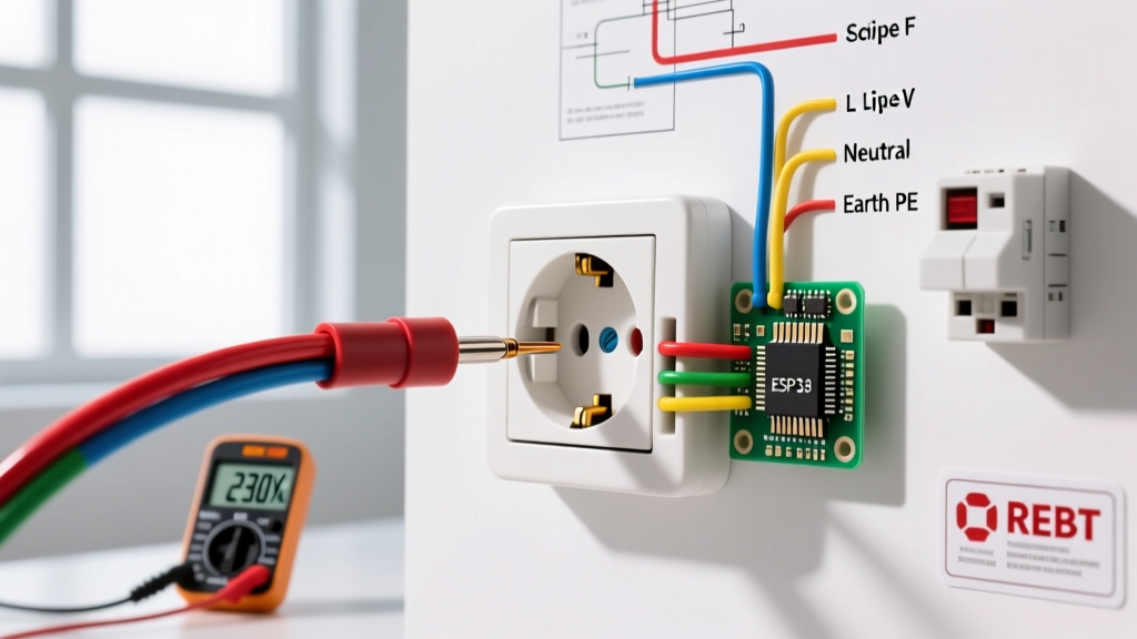
This wiring diagram reference dissects the two primary configurations: the half-switched (half-hot) receptacle and the fully switched receptacle. We will cover exact termination procedures, 2026 National Electrical Code (NEC) compliance matrices, and specific torque requirements to ensure a professional-grade installation.
Wiring Diagram Reference: Topology Breakdown
Before pulling wire, you must define the operational requirement of the room. The physical wiring changes drastically depending on whether one or both halves of the duplex receptacle need to be controlled by the wall switch.
Scenario A: The Half-Switched (Half-Hot) Receptacle
In this configuration, the top half of the outlet is controlled by the wall switch, while the bottom half remains constantly energized (always hot) for devices like phone chargers or air purifiers.
- Cable Requirement: 14/3 NM-B (or 12/3 NM-B for 20A circuits) running from the switch box to the outlet box.
- Switch Box Termination: The incoming constant hot (black) is pigtailed to the switch's line terminal and the 14/3 black wire. The switch's load terminal connects to the 14/3 red wire. All neutrals (white) are wire-nutted together and bypass the switch.
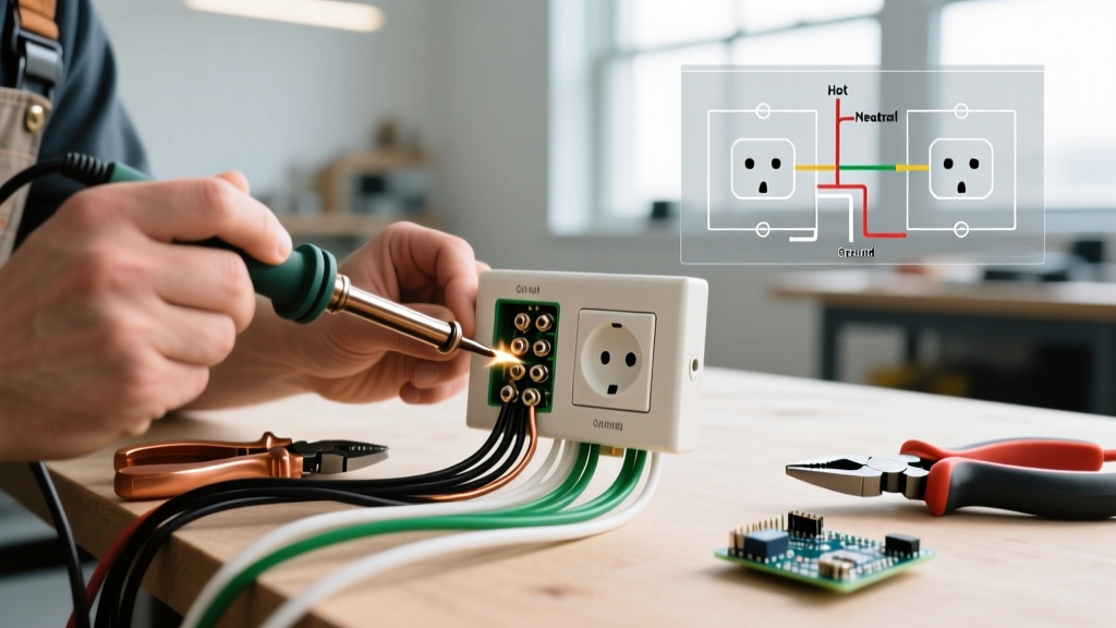
- Outlet Box Termination: The brass side (hot side) of the receptacle's connecting fin must be snapped off using needle-nose pliers. The 14/3 black wire (constant hot) terminates on the bottom brass screw. The 14/3 red wire (switched hot) terminates on the top brass screw. The white neutral connects to the silver side (fin remains intact).
Scenario B: The Fully Switched Receptacle
Here, the entire duplex outlet is dead until the wall switch is toggled. This is common in older homes or specific utility spaces where a single heavy-duty lamp or appliance is switched.
- Cable Requirement: Standard 14/2 NM-B (or 12/2 NM-B) is sufficient.
- Switch Box Termination: Incoming hot connects to the switch line terminal. The 14/2 white wire (re-identified with black electrical tape to denote it as a switched hot, per NEC 200.7(C)) connects to the switch load terminal.
- Outlet Box Termination: The brass fin remains intact. The incoming constant hot (black) connects to the brass screw. The re-identified white wire (switched hot returning from the switch) connects to the other brass screw. The bare ground bonds to the green screw and the metal box (if applicable).
2026 NEC Code Compliance Matrix
The Electrical Safety Foundation International (ESFI) heavily emphasizes adherence to the latest NEC iterations. When installing a switched electrical outlet in 2026, you must account for Arc-Fault Circuit Interrupter (AFCI) and Ground-Fault Circuit Interrupter (GFCI) mandates based on room topology.
| Room / Location | Breaker Protection Required | Receptacle Type Required | NEC Article Reference |
|---|---|---|---|
| Living Room / Family Room | Combination-Type AFCI | Standard 15A/20A Tamper-Resistant (TR) | 210.12(A) & 406.12(A) |
| Bedrooms | Combination-Type AFCI | Standard 15A/20A TR | 210.12(A) & 406.12(A) |
| Kitchens (Countertop) | GFCI (Breaker or Receptacle) | 20A GFCI TR (Switching rare here) | 210.8(A)(6) & 210.52(B) |
| Garages & Outdoors | Both AFCI and GFCI | 20A GFCI TR (Weather-Resistant WR) | 210.8(A)(2) & 210.12 |
Bill of Materials & Tooling Specifications
To execute this wiring diagram safely and to professional standards, avoid generic hardware store bins. Source the following specific components:
- Receptacle: Leviton 5262-SW 15-Amp Duplex Receptacle (approx. $4.50). Features easy-break brass fins and back-wire clamps for superior termination.
- Switch: Lutron Maestro MACL-153M (approx. $28.00) if dimming LED lamps on the switched half, or a standard Leviton 5601-2W 15A Single-Pole Toggle (approx. $2.10) for simple on/off.
- Cable: Southwire 14/3 SIMpull NM-B (approx. $0.48 per linear foot in 2026). The color-coded jacket prevents insulation damage during stripping.
- Wire Strippers: Klein Tools 11055 (10-20 AWG). Essential for scoring exactly 3/4 inch of insulation without nicking the copper conductor.
- Torque Screwdriver: Gardner Bender GTR-6000. NEC 110.14(D) mandates calibrated torque for terminations. Set to 14 in-lbs for standard 15A Leviton terminal screws.
Step-by-Step Termination Procedure
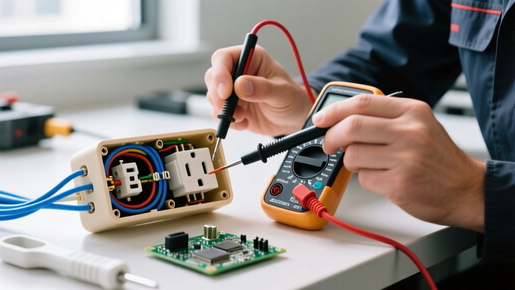
- De-energize and Verify: Turn off the 15A or 20A breaker at the main panel. Use a non-contact voltage tester (e.g., Fluke 1AC-II) and a multimeter to verify 0.0V between hot, neutral, and ground at both the switch and outlet boxes.
- Prepare the Conductors: Strip exactly 3/4 inch of insulation from the 14 AWG wires. Leaving more than 3/4 inch exposes bare copper outside the terminal yoke (a severe shock hazard); leaving less results in insulation being trapped under the screw head, causing a high-resistance connection and eventual thermal failure.
- Break the Hot Tab (Half-Hot Only): Using heavy-duty needle-nose pliers, grip the small brass connecting fin between the top and bottom brass screws. Bend it back and forth until it snaps cleanly. Never break the silver (neutral) tab unless you are splitting a 240V multi-wire branch circuit (MWBC), which requires a different diagram entirely.
- Form the Shepherd's Hook: Bend the stripped copper into a clockwise hook using the 14 AWG hole on your wire strippers. The clockwise orientation ensures the screw tightens the loop around the terminal rather than pushing it outward.
- Terminate and Torque: Seat the wires on their respective terminals. Black to constant brass, Red to switched brass, White to silver, Bare to green. Tighten using your torque screwdriver set to 14 in-lbs until the tool clicks.
- Grounding the Box: If using metal junction boxes, you must run a 14 AWG bare copper pigtail from the ground wire bundle to the box's green grounding screw, in addition to grounding the receptacle itself.
Advanced Troubleshooting & Edge Cases
Expert Warning: The most common failure mode in a switched electrical outlet installation is the 'Dead Half' scenario. If the bottom half of the outlet works but the top half remains dead regardless of switch position, 90% of the time the installer either forgot to break the brass tab (causing the constant hot to backfeed the switched half, rendering the switch useless) or broke the silver tab by mistake, severing the neutral return path for the switched half.
Edge Case: AFCI Breaker Nuisance Tripping
If your newly wired half-hot outlet causes a Combination-Type AFCI breaker to trip immediately upon energizing the circuit, check for a 'Bootleg Neutral'. This occurs when the switch box shares a neutral wire from a completely different circuit. AFCI breakers monitor the vector sum of current on the hot and neutral; if the switched hot draws current but the neutral returns via another circuit's path, the AFCI detects an imbalance and trips. Always ensure the neutral paired with the 14/3 cable originates from the exact same breaker as the hot conductors.
Edge Case: Dimmer Switch Flickering
When pairing a switched electrical outlet with a smart or LED dimmer switch (like the Lutron Maestro mentioned above), you may experience LED flickering at low dimming levels. This happens because the outlet's constant hot side powers a device (like a smart TV or phone charger) that introduces high-frequency noise onto the shared neutral. To resolve this, install a Lutron LUT-MLC (Minimum Load Capacitor) across the switched hot and neutral at the receptacle to stabilize the dimmer's internal electronics.