
The Schematic Approach to Electrical Outlet Issues
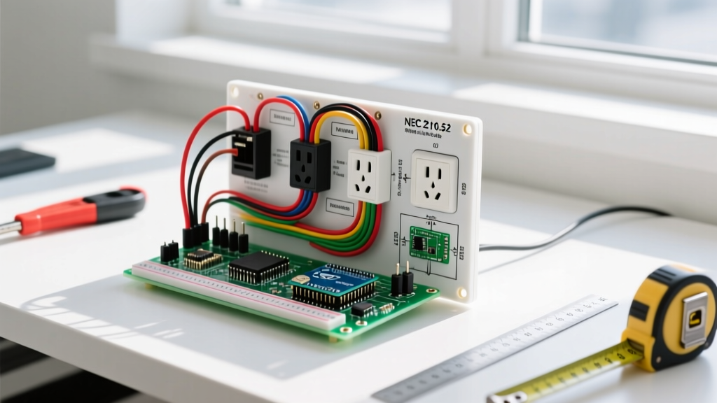
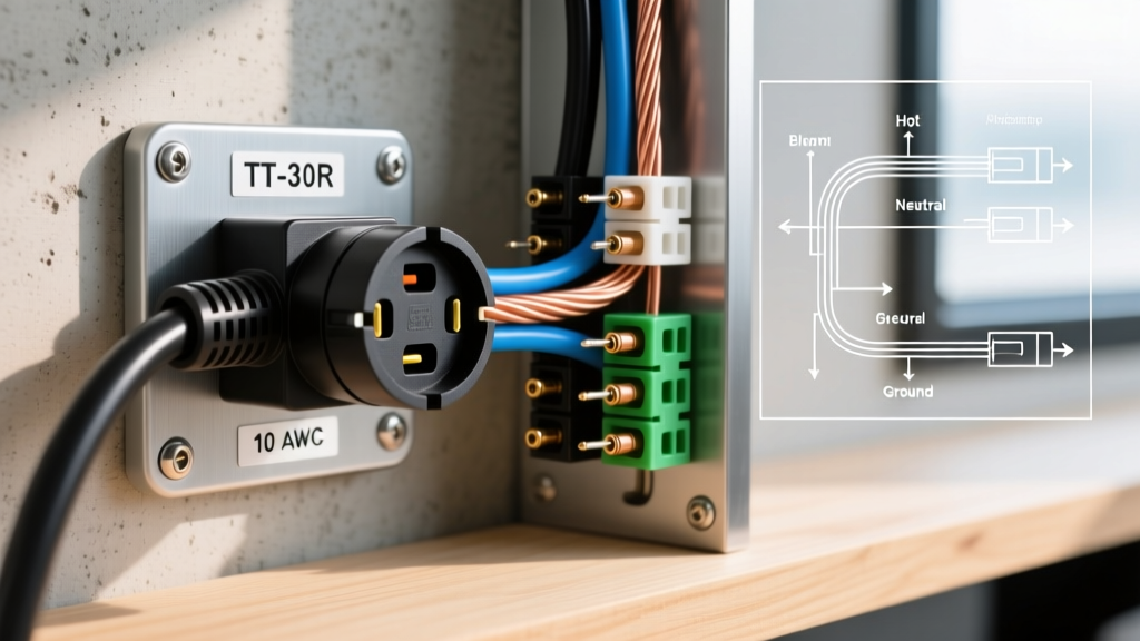
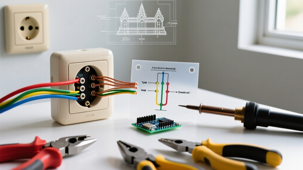
Most homeowners and novice DIYers treat electrical outlet issues as a simple 'swap the device' fix. However, when a standard 15A duplex receptacle fails repeatedly, a GFCI refuses to reset, or a breaker trips under moderate load, the root cause almost always lies in the circuit topology. By cross-referencing physical symptoms with standard NEC-compliant wiring diagrams, you can isolate faults in minutes rather than hours. Guessing leads to melted wires, tripped arcs, and severe shock hazards. In this wiring diagram reference guide, we map the most common electrical outlet issues to their exact schematic nodes, providing actionable troubleshooting steps using industry-standard tools and specific receptacle models.
Symptom-to-Schematic Fault Matrix
Before opening a single junction box, use this diagnostic matrix to narrow down your electrical outlet issues based on the physical behavior of the circuit. This table maps the symptom to the specific wiring diagram node you need to inspect.
| Physical Symptom | Probable Schematic Fault | Diagram Node to Check | Required Diagnostic Tool |
|---|---|---|---|
| Top half dead, bottom works | Split-receptacle brass tab intact or missing switched leg | Receptacle brass (hot) side fin | Continuity tester / Multimeter |
| GFCI trips immediately upon reset | Line/Load reversal or downstream ground fault | GFCI LINE vs LOAD terminals | Fluke 117 Multimeter |
| Breaker trips when plugging in high-draw appliance | Loose neutral creating high resistance or MWBC overload | Neutral bus or pigtail splice | Klein Tools RT250 Receptacle Tester |
| Receptacle faceplate feels warm to touch | Backstabbed push-in connections failing under continuous load | Terminal screws vs push-in holes | Infrared thermometer |
Deep Dive 1: The 'Half-Hot' Split-Receptacle Failure
One of the most frequently misunderstood electrical outlet issues occurs in living rooms and bedrooms where the top half of a receptacle is controlled by a wall switch, while the bottom half remains constantly hot. In a standard wiring diagram for this setup, a 12/3 NM-B (or 14/3 for 15A circuits) cable is run from the switch to the receptacle. The black wire carries constant 120V, the red wire carries the switched 120V, and the white wire serves as the shared neutral.
The Brass Tab Error
The most common failure point here is the brass fin (break-off tab) on the hot side of the receptacle. If you are replacing a standard Leviton 5362 (approx. $3.50) and forget to snap off this brass tab, both the top and bottom outlets will be tied together. Depending on how the switch is wired, this either results in the switch controlling both outlets, or worse, creates a direct dead short between the constant hot and the switched hot when the toggle is flipped, instantly tripping the breaker.
Expert Troubleshooting Tip: If your top outlet is dead but the bottom works, use a non-contact voltage tester to check the red wire in the wall box. If the red wire is hot when the switch is ON, but the top outlet is dead, the brass tab on your new receptacle was not removed, or the internal brass busbar was damaged during installation.
Deep Dive 2: GFCI Line vs. Load Topology Confusion
Ground Fault Circuit Interrupter (GFCI) receptacles are required by the National Fire Protection Association (NFPA) in wet locations like kitchens, bathrooms, and garages. A persistent electrical outlet issue with GFCIs is the device refusing to reset or failing to protect downstream outlets. This is almost universally caused by a Line/Load reversal in the wiring diagram.
Understanding the Internal Schematic
Inside a GFCI like the Eaton GFTR15-W ($18.00), there is a differential current transformer that monitors the current flowing out on the hot wire and returning on the neutral wire. If it detects a variance of just 5 milliamps (mA)—indicating current is leaking to ground, possibly through a person—it trips the circuit in under 25 milliseconds.
- LINE Terminals: These connect to the incoming power from the breaker panel.
- LOAD Terminals: These feed power to downstream standard receptacles, extending GFCI protection to the rest of the circuit.
Deep Dive 3: Multi-Wire Branch Circuits (MWBC) & Shared Neutrals
The most dangerous electrical outlet issues arise when an amateur DIYer replaces a standard duplex receptacle on a Multi-Wire Branch Circuit (MWBC) without understanding the schematic. An MWBC uses two hot wires (typically black and red) from opposite phases of the panel, sharing a single white neutral wire. Because the two hots are 180 degrees out of phase, their return currents cancel each other out on the neutral, preventing the neutral wire from overloading.
The 240V Catastrophe
According to NEC Article 210.4, MWBCs require a simultaneous disconnect (a handle tie, such as the Leviton 13113, approx. $1.25) to ensure both breakers are turned off at once. If you turn off only one breaker to replace an outlet, the shared neutral is still carrying the return current from the adjacent active circuit. More critically, if you are replacing a split-wired receptacle on an MWBC and you break off the silver (neutral) tab without installing a neutral pigtail, you interrupt the neutral path for the downstream circuit. The downstream devices will then attempt to complete their circuit in series across the two 120V hot legs. Instead of 120V, your television or laptop charger will suddenly receive 240V, instantly destroying the electronics and creating a severe fire hazard.
Deep Dive 4: Backstab vs. Screw Terminal Degradation
Thermal expansion and contraction cause some of the most insidious electrical outlet issues. Many modern receptacles feature 'backstab' or push-in wiring holes on the back of the device. These rely on a single spring-metal tang to grip the stripped 12 or 14 AWG copper wire. While UL-listed and legal, master electricians universally avoid them for high-draw circuits.
When a 12A continuous load (like a 1500W space heater or a window AC unit) is plugged in, the wire heats up. The thermal expansion causes the copper to slightly yield the spring tang. When the appliance is turned off and the wire cools, the connection becomes microscopically looser. Over a few years, this creates high electrical resistance. High resistance generates exponential heat, eventually melting the polycarbonate face of the receptacle or causing an arc fault. Always use the side-wiring screw terminals, wrapping the stripped wire clockwise around the screw so the tightening action pulls the loop closed. For 12 AWG wire, use a torque screwdriver set to the manufacturer's specification (typically 12-14 in-lbs) to ensure a perfect mechanical bond.
Essential Tools for Schematic Verification
To properly diagnose these issues, you must move beyond cheap plug-in testers. Invest in professional-grade diagnostic equipment:
- Fluke T6-1000 Electrical Tester: Allows you to measure voltage and current through the wire insulation using FieldSense technology, reducing the risk of arc flash from exposed probes.
- Klein Tools RT250 GFCI Receptacle Tester: Features a large LCD screen that not only identifies standard wiring faults (open ground, reverse polarity) but also displays the exact time to trip for GFCI circuits, helping you identify degrading internal sensing coils before they fail completely.
- Wago 221 Lever-Nuts: For repairing damaged pigtails or fixing MWBC neutral interruptions, these transparent lever connectors allow you to verify full wire insertion and provide a vibration-proof connection superior to traditional wire nuts.
Safety and Compliance
Before opening any junction box to address electrical outlet issues, always shut off the breaker and verify the absence of voltage using a contact meter. The Occupational Safety and Health Administration (OSHA) and the Consumer Product Safety Commission (CPSC) consistently report that failure to verify de-energized circuits is the leading cause of residential electrical injuries. By respecting the wiring diagram, understanding the topology of your circuits, and using the correct termination methods, you can permanently resolve outlet faults and ensure a safe, code-compliant electrical system.