
Understanding the France Electrical Outlet Type E Standard
When referencing the standard France electrical outlet type, electricians, inspectors, and advanced DIYers are dealing exclusively with the Type E receptacle (technically designated as CEE 7/5). Unlike the German Schuko (Type F) which relies on lateral grounding clips, the French standard integrates a protruding male earth pin directly on the socket face. This design mandates a specific mating plug (CEE 7/6) featuring a corresponding female earth aperture. As of 2026, strict adherence to the NF C 15-100 electrical code is enforced by Consuel (the French national electrical safety certification body), making precise wiring, correct wire gauge selection, and proper polarity non-negotiable for both new builds and legacy renovations.
Type E Quick Specifications (NF C 15-100)
- Nominal Voltage: 230V AC (±10% tolerance)
- Frequency: 50 Hz
- Max Current Rating: 16A (standard circuits) / 20A (dedicated heavy-load circuits)
- Mandatory Wire Gauge: 2.5 mm² solid copper (minimum for all socket outlets)
- Circuit Breaker Protection: 16A or 20A Type C or D curve
- Child Safety: Integrated mechanical shutters (alvéoles de sécurité) are strictly mandatory
Anatomy and Pin Configuration
The physical geometry of the France electrical outlet type E is designed to prevent the insertion of incompatible, ungrounded plugs while ensuring the earth connection is established before the live conductors make contact. The socket features two 4.8mm diameter holes for Phase and Neutral, spaced 19mm apart, alongside a 4.8mm male earth pin projecting outward. According to the IEC World Plugs standard documentation, this configuration ensures that when a compatible CEE 7/6 or hybrid CEE 7/7 plug is inserted, the earth pin engages the plug's internal grounding clip first, providing a critical safety path for fault currents before the energized pins connect.
Harmonized vs. Legacy Wire Colors
A major hurdle in wiring French outlets is encountering legacy installations. Prior to the European harmonization of cable colors in the late 1970s and early 1980s, French wiring utilized different color codes. When upgrading old outlets to modern Type E receptacles, you must verify the actual conductors with a CAT III or CAT IV multimeter, as legacy colors can be highly misleading and pose a severe shock hazard.
Wiring Diagram & Terminal Mapping Reference
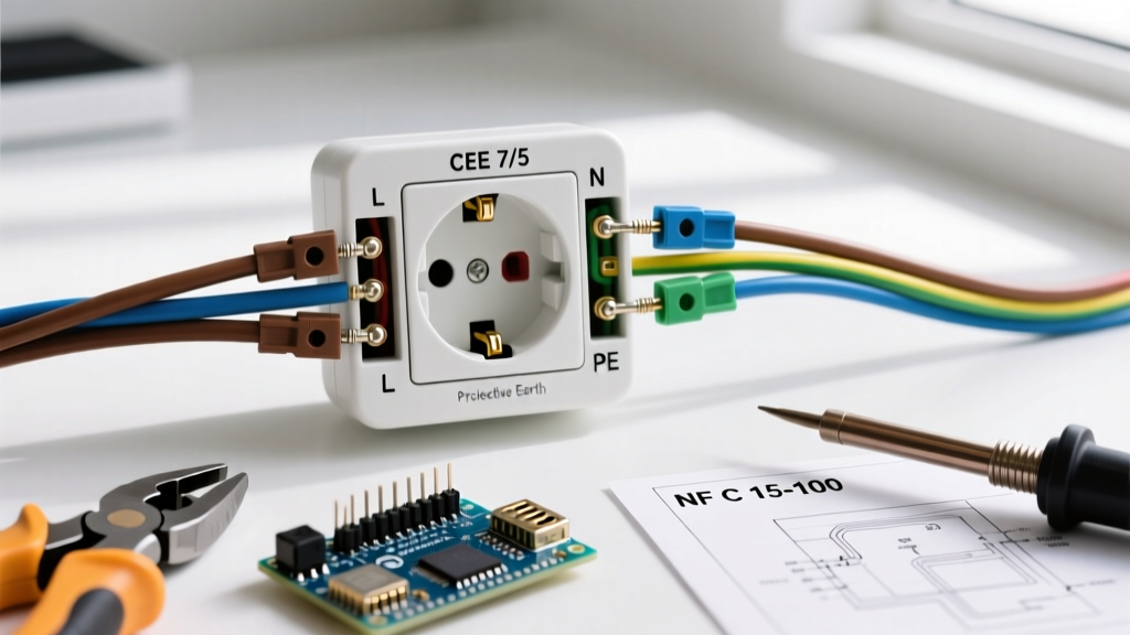
Proper polarity is a critical pass/fail metric during a Consuel inspection. Looking directly at the face of the installed Type E socket, the NF C 15-100 standard dictates a specific orientation for the terminal connections. Reversing the Phase and Neutral will not prevent an appliance from operating, but it creates a lethal edge case: if a single-pole switch inside the appliance breaks only the neutral line, the internal components remain energized at 230V even when turned off.
| Terminal Marking | Function | EU Harmonized Color | Pre-1980 Legacy Color | Position (Facing Socket) |
|---|---|---|---|---|
| L | Phase (Line) | Brown (or Red) | Green / Yellow / Grey | Right Side |
| N | Neutral | Blue | Light Blue / White | Left Side |
| PE / ⏚ | Protective Earth | Green/Yellow Stripe | Bare Copper / Red | Top (Male Pin) |
Step-by-Step Installation Procedure
Installing a Type E outlet requires precision. The NF C 15-100 standard mandates specific strip lengths and torque settings to prevent arcing, thermal runaway, and loose connections over time. Follow this exact sequence for a compliant installation:
- Isolate and Verify: Switch off the 16A/20A circuit breaker at the main tableau électrique. Use a non-contact voltage tester, followed by a calibrated multimeter (set to AC Voltage), probing between Phase and Neutral, Phase and Earth, and Neutral and Earth to confirm 0V.
- Prepare the Conductors: Using a calibrated wire stripper, remove exactly 12mm of insulation from the 2.5 mm² solid copper wires. Do not score the copper conductor, as this creates a stress fracture point that will snap under terminal screw torque.
- Connect Protective Earth (PE) First: Insert the Green/Yellow wire into the terminal linked to the protruding male earth pin. Tighten to 0.8 Nm. Safety protocols dictate that the earth wire must always be connected first and disconnected last to ensure continuous grounding during maintenance.
- Connect Neutral (N) and Phase (L): Insert the Blue wire into the left terminal (N) and the Brown wire into the right terminal (L). Tighten both to 0.8 Nm. Perform a physical 'pull test' (applying roughly 30N of force) to ensure the wires are seated firmly and no bare copper is exposed outside the terminal block.
- Mounting and Flush Box Depth: Secure the receptacle chassis into the flush-mounted box using the M4 mounting screws. The NF C 15-100 code requires a minimum box depth of 40mm (50mm is highly recommended in 2026 to accommodate smart sockets or Wago connectors) to prevent wire crushing and insulation damage against the back of the socket mechanism.
- Final Verification: Re-energize the circuit and test with a dedicated Type E socket tester (which features a female earth contact to verify the male pin's continuity back to the main earth bar).
Common Wiring Faults & Troubleshooting
Even experienced DIYers make critical errors when adapting to the France electrical outlet type E standard. Below are the most frequent failure modes encountered during Consuel inspections and their technical resolutions.
- Floating Earth on Legacy Circuits: In pre-1990 French apartments, you may find a 2.5 mm² circuit that lacks a dedicated earth wire, or worse, an earth wire tied to a metallic water pipe. The NF C 15-100 strictly forbids using plumbing as a ground. Resolution: You must pull a new 2.5 mm² 3-core cable (including Green/Yellow PE) all the way back to the main earth terminal block (barrette de terre) in the electrical panel.
- Undersized Wiring on 20A Breakers: Some installers attempt to wire standard socket circuits using 1.5 mm² wire protected by a 20A breaker. This is a severe fire hazard. 1.5 mm² wire is strictly limited to 16A (and typically reserved for lighting circuits). Resolution: All socket outlets must use a minimum of 2.5 mm² wire. If 1.5 mm² is found, the breaker must be downgraded to 10A, and the circuit restricted to a maximum of 5 socket outlets, though 2.5 mm² is the universal best practice.
- Reversed Polarity (Phase/Neutral Swap): As mentioned, appliances will function, but single-pole appliance switches will break the neutral instead of the phase. Resolution: Swap the Brown and Blue wires at the terminal block. Always verify with a phase-sequence tester.
Expert Warning: Never file down or remove the protruding male earth pin on a Type E socket to accommodate a foreign plug. This destroys the primary safety mechanism of the France electrical outlet type and will result in an automatic failure during any real estate diagnostic électrique (electrical safety diagnostic required for property sales in France).
Frequently Asked Questions (FAQ)
Can I install a German Schuko (Type F) socket in France?
While the hybrid CEE 7/7 plug (which has both the female earth hole for Type E and the lateral earth clips for Type F) is ubiquitous across Europe, installing a pure Type F (Schuko) socket in a French residence is generally discouraged and may fail a strict Consuel inspection. The French standard explicitly requires the socket to provide the male earth pin to guarantee the grounding of older, non-hybrid French plugs. Always install a true CEE 7/5 (Type E) socket for guaranteed compliance.
What is the maximum number of Type E sockets allowed on a single circuit?
According to the latest NF C 15-100 amendments, a circuit protected by a 16A breaker using 2.5 mm² wire can support up to 8 socket outlets. If the circuit is protected by a 20A breaker (also using 2.5 mm² wire), you can install up to 12 socket outlets. Note that a double or triple gang socket counts as a single outlet point for this calculation, provided they share a single flush box.
Do I need a specialized breaker for kitchen Type E outlets?
Yes. The kitchen requires dedicated circuits. The oven must have its own dedicated 20A circuit (wired with 2.5 mm² or 6 mm² depending on the manufacturer's exact kW draw), and the cooking hob requires a dedicated 32A circuit using 6 mm² wire, terminating in a specialized high-amperage connection box rather than a standard Type E socket. Standard kitchen counter Type E sockets for small appliances must be on a separate 20A circuit, with a minimum of 6 outlets provided.
For further reading on official housing electrical safety requirements and certification processes, refer to the French Government Service-Public portal on electrical diagnostics and the official Consuel certification guidelines. Ensuring your wiring diagrams and physical installations align perfectly with these standards guarantees both safety and regulatory compliance.