
Decoding the Receptacle: A Schematic Approach to Outlet Repair
When a receptacle stops working, most DIYers immediately swap the device without understanding why it failed. Learning how to fix an electrical outlet requires more than just matching wire colors; it demands a mental wiring diagram. By visualizing the internal schematic of a standard NEMA 5-15R or 5-20R duplex receptacle, you can pinpoint failure modes—like open neutrals, degraded push-in terminals, or broken split-circuit tabs—in minutes.
According to the U.S. Consumer Product Safety Commission (CPSC), faulty receptacles and loose connections are leading causes of residential electrical fires. In 2026, adherence to NEC (NFPA 70) torque specifications and tamper-resistant (TR) mandates is stricter than ever. This guide translates physical outlet anatomy into schematic logic to help you troubleshoot and repair with professional precision.
Essential Diagnostic Tools & Safety Protocols
Before touching a single terminal screw, establish a safe lockout/tagout environment. Never rely solely on a wall switch to de-energize a circuit.
- Voltage Tester: Fluke 1AC-II VoltAlert (approx. $35) for non-contact verification.
- Receptacle Tester: Klein Tools RT250 (approx. $45) to read GFCI and wiring fault codes.
- Wire Strippers: Klein Tools 11054E (10-20 AWG) to clean up damaged conductor ends.
- Torque Screwdriver: Required by modern NEC codes for terminal verification (typically 12-14 in-lbs for 15A/20A devices).
- Replacement Device: Leviton T5252-W 15A Tamper-Resistant Duplex (approx. $2.50) or Eaton GFNT1-W for GFCI applications.
CRITICAL SAFETY WARNING: Always verify the circuit is dead at the outlet using a proven voltage tester. Test a known live circuit first to ensure your tester's battery is functional, then test the target outlet, then re-test the known live circuit (Live-Dead-Live protocol).
The Internal Wiring Diagram: Mapping Terminals to Conductors
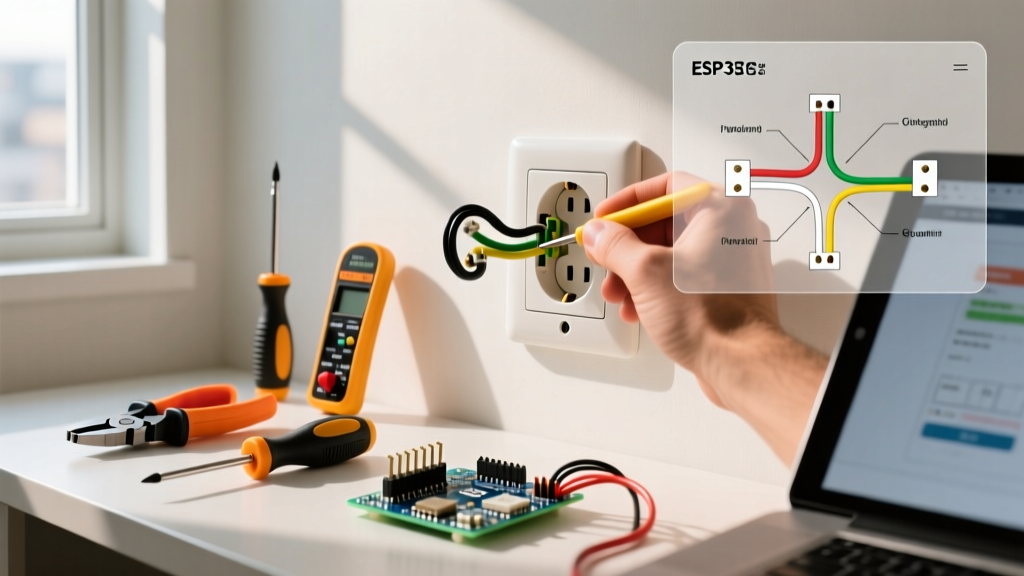
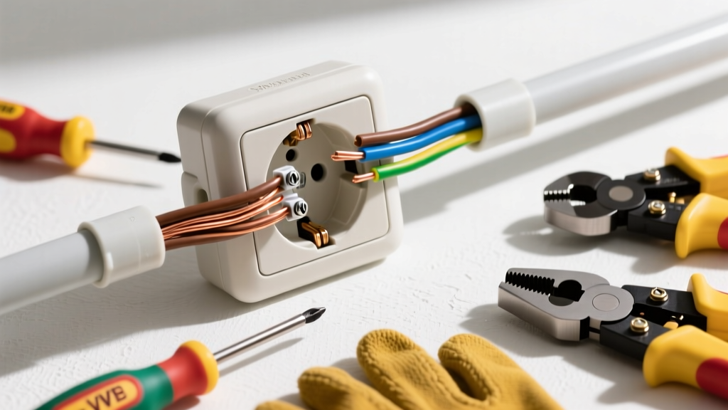
To understand how to fix an electrical outlet, you must map the physical brass, silver, and green screws to their schematic equivalents. A standard duplex receptacle is essentially two parallel loads connected by internal metal bus bars (the side fins).
| Terminal Color | Schematic Designation | Wire Color (US) | Function & Failure Mode |
|---|---|---|---|
| Brass | Line / Hot (Ungrounded) | Black (or Red) | Carries 120V AC. Failure here causes a complete dead outlet or reversed polarity if swapped. |
| Silver | Neutral (Grounded) | White | Return path. An 'open neutral' is the most common cause of intermittent power or downstream dead outlets. |
| Green | Equipment Ground | Bare Copper / Green | Safety fault path. Never carries current unless a short-circuit fault occurs. |
Diagnosing the 'Big Three' Outlet Failures via Schematic Logic
1. The 'Backstab' Push-In Terminal Failure
Look at the back of a cheap builder-grade receptacle. You will see small holes next to the screw terminals. These are push-in (backstab) connections. Schematically, these rely on a tiny internal spring-steel wedge to grip the 14 AWG wire. Over years of thermal expansion and contraction (from drawing 12A-15A loads like space heaters), the spring loses tension. The connection arcs, melts the plastic housing, and fails.
The Fix: Never use backstab holes. When repairing, cut off the damaged wire end, strip 3/4 inch of fresh insulation using your Klein 11054E, and wrap the wire clockwise around the brass/silver screw terminal. Tighten to 14 in-lbs.
2. The Broken Split-Circuit Tab (Half-Hot Receptacle)
In many living rooms, the top half of an outlet is controlled by a wall switch, while the bottom half is always hot. Schematically, this requires breaking the connecting metal fin (tab) on the brass (hot) side only. If an outlet suddenly stops working entirely, or if both halves are dead when they should be split, a previous DIYer may have accidentally snapped the neutral (silver) tab, or failed to break the hot tab when replacing a split-wired device.
The Fix: Inspect the side fins. If the circuit requires a split receptacle, use needle-nose pliers to snap off the brass fin. Leave the silver neutral fin intact to maintain a continuous neutral return path for both halves.
3. The Open Neutral Cascade
Because outlets are typically wired in a daisy-chain (parallel) schematic, the neutral wire entering the outlet also feeds the next outlet downstream via a pigtail or a second silver screw. If the neutral connection at Receptacle A fails, Receptacles B, C, and D will also die, even though their hot wires are still energized.
The Fix: Use your RT250 tester. If it shows 'Open Neutral', trace the schematic backward. Open the suspected upstream outlet and secure the white wires under the silver screws, ensuring no bare copper is exposed outside the terminal and no insulation is trapped under the screw head.
Step-by-Step Physical Repair Protocol
- De-energize & Verify: Turn off the breaker. Execute the Live-Dead-Live test.
- Extract & Inspect: Unscrew the faceplate and device yoke. Pull the receptacle out. Look for scorch marks, melted PVC, or exposed stranded wire.
- Prep Conductors: If wires are brittle or scored from previous backstab use, snip them back. Re-strip to exactly 3/4 inch.
- Form the J-Hook: Bend the solid copper wire into a tight 'J' shape. Hook it around the screw clockwise. This ensures that tightening the screw pulls the wire loop tighter, rather than pushing it out.
- Torque & Seat: Tighten the terminal screw. If using a torque screwdriver, set it to the manufacturer's spec (usually printed on the device box, typically 12-14 in-lbs for Leviton/Eaton 15A devices).
- Ground Verification: Ensure the bare ground wire is securely fastened to the green screw and, if in a metal box, that a grounding pigtail connects the box to the device.
- Test: Push the device back into the box carefully, ensuring no wires are pinched. Restore power and test with the RT250.
Advanced Schematic Nuance: GFCI Line vs. Load
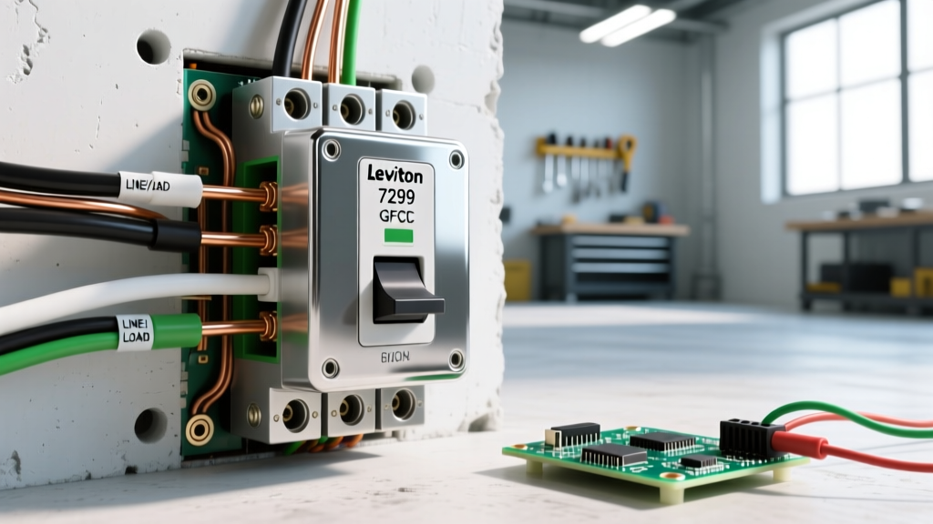
When fixing a GFCI outlet (like the Leviton GFNT1-W), the wiring diagram becomes critical. GFCIs have two distinct terminal sets: LINE and LOAD.
- LINE: Connects to the incoming power from the breaker panel.
- LOAD: Connects to downstream outlets to extend ground-fault protection.
If you wire the incoming power to the LOAD terminals, the GFCI will not reset, or it will function locally but fail to protect downstream devices. Always use the included warning tape to cover the LOAD terminals if you are only wiring a single-point GFCI. For comprehensive safety standards regarding ground-fault protection, refer to the NFPA 70 National Electrical Code guidelines on GFCI placement in damp and wet locations.
Frequently Asked Questions
Why does my outlet spark when I plug something in?
A small blue spark is normal inductive arcing when plugging in a high-draw device (like a vacuum) that is already switched 'on'. However, a large orange spark accompanied by a popping sound indicates a loose terminal connection or degraded internal bus bar. Replace the receptacle immediately.
Can I use a 20A receptacle on a 15A breaker?
No. While a 15A receptacle (NEMA 5-15R) is permitted on a 20A circuit (provided there are multiple outlets on the run), a 20A receptacle (NEMA 5-20R, featuring the T-shaped neutral slot) is strictly prohibited on a 15A breaker. The breaker would not adequately protect the 20A-specific appliance you might plug into it. Consult OSHA electrical safety guidelines and NEC Article 210 for exact receptacle-to-circuit rating matrices.
What is the purpose of the red wire in my outlet box?
In a standard 12/3 or 14/3 Romex cable, the red wire is a secondary hot conductor. Schematically, it is used for 240V baseboard heaters, 3-way switch travelers, or multi-wire branch circuits (MWBC) / split-wired half-hot outlets. Never cap it off without tracing its origin first.