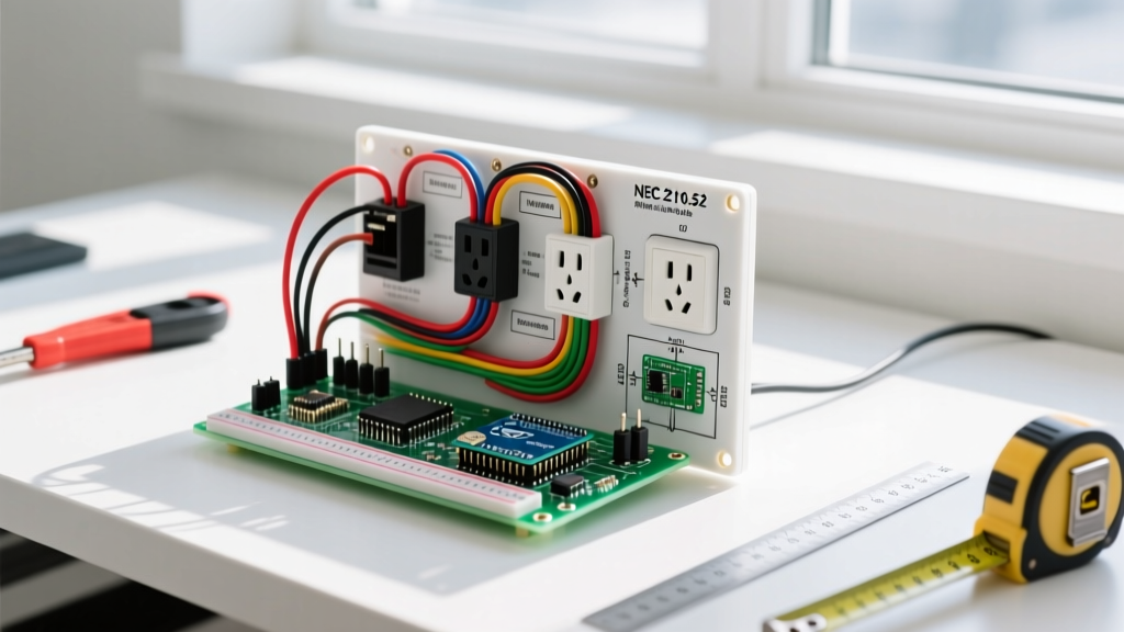
The Modern Vehicle Power Hub: 12V vs. 120V Outlets
If you are dealing with a car electrical outlet not working, the frustration usually stems from a misdiagnosis of the outlet type. Modern vehicles feature two distinct power delivery systems: the legacy 12V DC accessory socket (commonly called the cigarette lighter port) and the increasingly common 120V AC inverter outlets found in modern EVs, hybrids, and trucks with Vehicle-to-Load (V2L) capabilities. Diagnosing a failure requires entirely different approaches, tools, and safety protocols for each system.
This inspection and testing guide will walk you through pinpointing the exact failure mode—whether it is a melted bimetallic strip in a 12V socket, a blown Micro2 fuse, or a tripped GFCI on a 120V bed outlet—using professional-grade diagnostic techniques.
Essential Tools for Automotive Outlet Diagnostics
Before dismantling dash panels or checking fuse boxes, gather the correct diagnostic equipment. Standard household tools are insufficient for the noisy electrical environment of a running vehicle.
- True-RMS Multimeter: A standard averaging multimeter will give inaccurate readings due to the AC ripple produced by automotive alternators. A True-RMS meter (like the Fluke 117 or Klein Tools MM700) is mandatory for accurate DC voltage and voltage-drop testing.
- Circuit Tester / Power Probe: A Power Probe IV allows you to inject power and ground directly into the socket to bypass vehicle wiring and verify the socket's physical integrity.
- Micro-Fuse Puller: Modern vehicles (2018 and newer) heavily utilize Micro2 (ATR) and MINI fuses. Standard pliers will snap the blades off these low-profile fuses.
- Thermal Camera (Optional but recommended): A smartphone-attached thermal imager (like the FLIR ONE Gen 3) instantly reveals high-resistance connections generating excess heat behind the dash.
Step-by-Step Inspection: 12V Accessory Sockets
The standard 12V accessory socket is rated for 120W to 180W (10A to 15A at 12V–14.4V). When a car electrical outlet not working issue arises on the 12V side, it is almost always due to physical degradation or an overloaded circuit.
1. Verifying the Bimetallic Strip and Center Contact
The most common physical failure is a loss of contact. The center pin provides the positive 12V feed, while the outer spring-loaded clips provide the ground. Over time, heat from high-draw accessories (like portable tire inflators or 150W inverters) causes the plastic housing to warp, pushing the center pin too far back for the accessory plug to make contact.
- Disconnect the negative battery terminal to prevent a dead short.
- Inspect the socket with a flashlight. If the center pin is recessed deeper than 3/8 of an inch, it has been pushed back.
- Use a wooden dowel or plastic trim tool to gently pry the center contact forward. Never use a metal screwdriver, as residual capacitor charge or accidental battery reconnection can cause a severe short.
2. Fuse Identification and Continuity Testing
Locate the cabin fuse panel (usually under the driver-side dash or in the passenger kick panel). Consult the owner's manual to identify the "CIG," "PWR OUT," or "ACC" fuse. Perform a voltage drop test across the fuse with the circuit under load, or remove the fuse and test for continuity. If you find a blown Micro2 or MINI fuse, replace it with the exact amperage rating. Never upsize a 10A fuse to 15A; the factory 16 AWG or 14 AWG feed wire will melt before a 15A fuse blows, creating a dash fire hazard.
3. Voltage Drop Testing on the Feed Wire
If the fuse is intact but the outlet is dead, the issue is high resistance in the wiring. According to SAE International automotive standards, voltage drop on a 12V accessory circuit should not exceed 0.5V under maximum rated load.
- Set your multimeter to DC Volts.
- Place the red probe on the battery positive terminal and the black probe on the center pin of the 12V socket.
- Plug in a known 5A load (like a high-power 12V fan).
- A reading above 0.5V indicates corroded splices, a failing fuse panel bus bar, or a pinched wire behind the dash.
Troubleshooting 120V AC Inverter Outlets (EVs & Modern Trucks)
Vehicles like the Ford F-150 PowerBoost (Pro Power Onboard), Rivian R1T, and Hyundai Ioniq 5 (V2L) feature 120V AC outlets. These are not fed by simple fuses; they are powered by high-voltage DC-to-AC inverters integrated into the vehicle's powertrain or battery management system.
GFCI Trips and Inverter Fault Codes
Because these outlets are often located in the truck bed or exterior panels, they are protected by Ground Fault Circuit Interrupters (GFCI) and strict inverter logic boards. If your 120V car electrical outlet not working issue occurs, check the following:
- GFCI Reset: Locate the TEST and RESET buttons on the outlet face. Moisture ingress or a faulty extension cord can trip the GFCI. Press TEST, then firmly press RESET.
- Inverter Thermal Shutoff: Inverters have strict thermal limits. If you are drawing 1,800W from a 2,000W bed outlet in 95°F ambient heat, the inverter's thermal management system will shed the load to protect the power electronics. Check the vehicle's infotainment screen for "Inverter Overload" or "Thermal Derate" warnings.
- Vehicle State Requirements: Many 120V systems require the vehicle to be in "Ready to Drive" mode or specifically have the "Pro Power" or "V2L" toggle enabled in the infotainment menu. The outlet will not energize if the vehicle is simply in "Accessory" mode.
Safety Warning: Never attempt to bypass a tripped GFCI or open a factory-sealed high-voltage inverter housing. For advanced multimeter techniques and safety protocols regarding mixed AC/DC environments, refer to Fluke's electrical testing guides. Always check the National Highway Traffic Safety Administration (NHTSA) database for electrical system recalls specific to your vehicle's make and model before modifying wiring.
Common Automotive Outlet Failure Modes & Solutions
| Symptom | Probable Cause | Diagnostic Step | Fix |
|---|---|---|---|
| Accessory plug falls out easily; intermittent power | Worn internal ground springs or warped housing | Visual inspection; wiggle test with 12V test light | Replace socket with heavy-duty marine-grade unit |
| Outlet dead; fuse blows immediately upon replacement | Dead short in feed wire or melted socket internals | Check continuity between center pin and chassis ground | Trace wiring harness; replace socket and damaged wire |
| 12V outlet works, but voltage drops to 10V under load | Undersized factory wire (16 AWG) or corroded ground | Perform voltage drop test on positive and ground legs | Rewire with 12 AWG wire and install inline 20A breaker |
| 120V bed outlet dead; no infotainment fault codes | Tripped GFCI or failed inverter relay | Press GFCI reset; listen for relay click under rear seat | Reset GFCI; if relay fails, scan for U-codes via OBD2 |
| Plastic burning smell near dash 12V socket | High-resistance connection arcing at the spade terminals | Thermal camera scan; inspect for brown/discolored plastic | Cut damaged wire back; crimp new high-temp spade connectors |
When to Rewire: Upgrading to Heavy-Duty Marine Sockets
Factory 12V sockets are notorious for failing when used with high-draw overlanding gear, portable fridges, or air compressors. If your diagnosis reveals that the factory socket is fundamentally inadequate (rather than just broken), upgrade to a Hella DIN standard socket or a ceramic-core 20A marine socket.
When performing the upgrade, abandon the factory push-tab connectors. Vibration in automotive environments causes solder joints to fatigue and snap. Instead, use adhesive-lined marine heat shrink and crimp the new 12 AWG silicone-jacketed wire directly to the socket's ring terminals. Install an inline 20A automatic-reset circuit breaker within 6 inches of the battery connection to protect your new heavy-duty wiring harness.
Final Verification
After completing repairs or replacements, reconnect the battery and perform a final load test. Plug in a 12V digital voltage monitor and run a high-draw accessory for 5 minutes. The voltage at the socket should remain above 11.8V (engine off) or 13.5V (engine running). For 120V systems, use a standard 3-prong GFCI outlet tester to verify correct wiring polarity and ground integrity before plugging in sensitive electronics like laptops or CPAP machines.