
The Critical Role of Proper Disconnection in Outlet Inspection
When conducting advanced electrical diagnostics, thermal imaging, or insulation resistance testing, you must completely isolate the circuit. Learning how to safely disconnect electrical outlet wiring is not merely about removing a faceplate; it is a systematic process of de-energization, verification, and physical isolation. According to the Occupational Safety and Health Administration (OSHA), failure to properly verify the absence of voltage before physical contact is a leading cause of residential and commercial arc flash incidents. This inspection guide details the exact protocols, specialized tooling, and edge-case troubleshooting required to disconnect a receptacle safely, adhering to the latest National Electrical Code (NEC) and NFPA 70E standards.
Mandatory Safety Protocols: PPE and Lockout/Tagout (LOTO)
Before touching any terminal screw, you must treat every conductor as energized. The NFPA 70E standard dictates that electrical workers must utilize appropriate Personal Protective Equipment (PPE) based on the incident energy level. For standard 120V/240V residential and light commercial receptacles, this typically means Category 1 or 2 PPE during the initial testing phase.
- Voltage-Rated Gloves: Class 00 rubber insulating gloves (rated for 500V AC) paired with leather protectors.
- Arc-Rated Face Shield: Minimum 8 cal/cm² rating for balaclava and face shield setups when testing live panels to identify the correct breaker.
- Lockout/Tagout (LOTO): Once the breaker is identified and switched off, apply a physical lock and tag to the panelboard breaker to prevent accidental re-energization by other occupants or workers.
Essential Diagnostic and Disconnection Toolkit
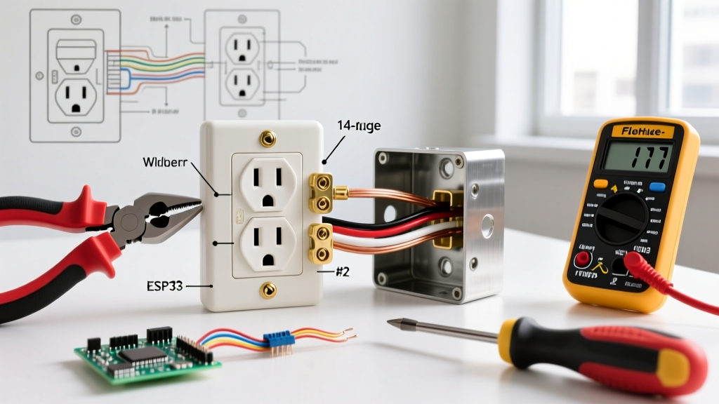
Using substandard testing equipment can yield false-negative voltage readings, leading to fatal assumptions. The Electrical Safety Foundation International (ESFI) strongly recommends using independently verified, CAT III or CAT IV rated diagnostic tools. Below is the professional toolkit required for this procedure.
| Tool Type | Recommended Model | Primary Purpose | Avg. Cost |
|---|---|---|---|
| True RMS Multimeter | Fluke 117 Electricians True RMS | Live-Dead-Live (LDL) voltage verification | $230 - $260 |
| NCV Tester | Klein Tools NCVT-2 | Initial non-contact voltage detection (12V-1000V) | $35 - $45 |
| Insulated Screwdriver | Wiha 32092 2-Piece Insulated Set | Safe removal of terminal screws and yoke | $25 - $35 |
| Receptacle Release Tool | Jonard Tools RT-1 | Releasing push-in (backstab) wire connections | $15 - $20 |
Step-by-Step: How to Disconnect Electrical Outlet Wiring
Step 1: Non-Contact Voltage Testing and Circuit Identification
Insert the Klein NCVT-2 into the top and bottom slots of the receptacle. A red LED and audible beep confirm the presence of voltage. Note which half of the outlet is live. Proceed to the main service panel, turn off the suspected branch circuit breaker, and re-test the outlet with the NCVT to confirm the correct breaker was tripped.
Step 2: Breaker Shutoff and Physical Lockout
Switch the identified breaker to the OFF position. Apply your LOTO device. If working in a shared residential environment, place a highly visible warning tag over the panel door indicating that electrical testing is in progress.
Step 3: The Live-Dead-Live (LDL) Verification Test
This is the most critical step. NCV testers can fail or be fooled by phantom voltage. You must use your Fluke 117 multimeter to perform an LDL test:
- Live: Test the multimeter on a known live source (e.g., an adjacent, confirmed live outlet or the main panel bus bars) to verify the meter and leads are functioning. You should read ~120V.
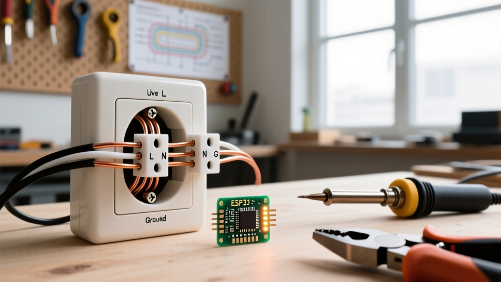
- Dead: Insert the probes into the target disconnected outlet. Test Hot (brass) to Neutral (silver), Hot to Ground (green/bare), and Neutral to Ground. All readings must be 0.00V or within a few millivolts of zero.
- Live: Return to the known live source and test again. This proves the meter's internal fuse or battery did not fail during the "Dead" test phase.
Step 4: Yoke Removal and Wire Disconnection
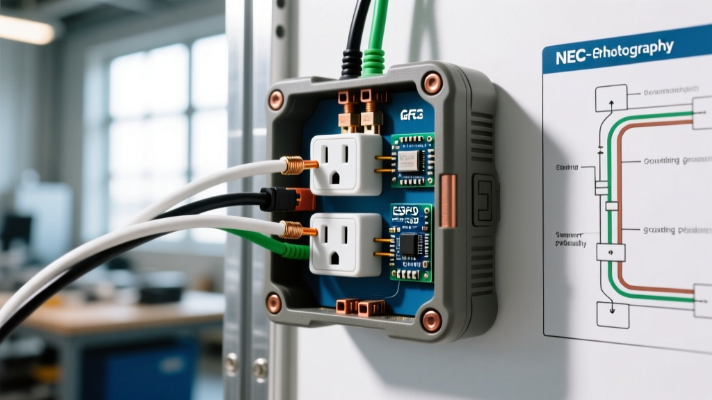
Remove the single center 6-32 mounting screw holding the faceplate. Remove the top and bottom 6-32 yoke screws securing the receptacle to the junction box. Gently pull the device out of the box, being careful not to stress the conductors.
For Terminal Screw Connections: Use your Wiha insulated Phillips #2 screwdriver to back out the brass and silver terminal screws counter-clockwise. Pull the solid copper wires straight out.
For Push-In (Backstab) Connections: Do not simply pull the wires, as this can damage the internal spring-loaded contacts or snap the conductor. Insert a small flathead screwdriver or the Jonard RT-1 tool into the small release slot adjacent to the wire hole. Depress the spring clip while gently pulling the wire free.
Navigating Edge Cases: MWBC and Switched Receptacles
Not all outlets are fed by a single standard 120V branch circuit. Failing to recognize complex wiring topologies can result in severe shock hazards even after the primary breaker is turned off.
Multi-Wire Branch Circuits (MWBC)
An MWBC shares a single neutral wire between two hot conductors on opposite phases (240V across the hots, 120V from each hot to neutral). If you only disconnect one breaker, the shared neutral may still be carrying return current from the other active phase. According to NEC Article 210.4, MWBCs must have a simultaneous disconnecting means (a 2-pole breaker or approved handle ties). Always test the neutral wire to ground with your multimeter before physically disconnecting the neutral terminal. If you read voltage, an adjacent breaker feeding the other half of the MWBC is still ON.
Split-Wired (Switched) Outlets
In living rooms and bedrooms, the top and bottom halves of a duplex receptacle are often fed by different circuits or a switch loop. The brass connecting tab on the hot side is broken off. You must verify the absence of voltage on both the top and bottom brass terminals independently before proceeding with disconnection.
Post-Disconnection Inspection Matrix
Once the outlet is fully disconnected and resting outside the junction box, conduct a thorough physical inspection. Use the following matrix to identify failure modes and determine corrective actions.
| Defect / Failure Mode | Visual or Tactile Cue | Corrective Action Required |
|---|---|---|
| Thermal Degradation | Browned, brittle, or melted wire insulation near the terminal. | Cut back damaged wire to clean copper. Replace receptacle. |
| Backstab Spring Failure | Wire pulls out easily without pressing the release tab; loose fit. | Never reuse backstab connections. Strip wire and use terminal screws. |
| Improper Stripping | Exposed copper visible past the terminal pad, or insulation nicked. | Re-strip wire using precision wire strippers to exact gauge depth. |
| Yoke Tab Fatigue | Plaster ears cracked or mounting yoke bent from overtightening. | Replace receptacle; do not attempt to bend yoke back into shape. |
Reconnection and NEC Torque Compliance
When your inspection and testing are complete, reconnecting the outlet requires adherence to modern code standards. NEC Article 110.14 mandates that electrical connections must be torqued to the manufacturer's specifications. Most standard 15A and 20A commercial-grade receptacles (such as the Leviton 5362 or Hubbell HBL5362) require between 0.5 N-m (4.4 in-lbs) and 0.8 N-m (7.1 in-lbs) of torque on the terminal screws.
Using a calibrated torque screwdriver, such as the Milwaukee 48-22-0012, ensures you do not under-torque (leading to high-resistance arcing faults) or over-torque (which strips the brass threads or cracks the thermoset housing). Wrap the wire clockwise around the terminal screw so that tightening the screw pulls the wire loop closed rather than pushing it out.
Summary
Knowing how to properly disconnect electrical outlet wiring is a foundational skill that bridges the gap between amateur DIY and professional electrical diagnostics. By strictly adhering to the Live-Dead-Live testing protocol, utilizing CAT III rated instrumentation, and remaining vigilant against edge cases like MWBCs, you ensure absolute safety during your inspection. Always prioritize verified de-energization over assumed safety, and never bypass the critical step of physical lockout.