
The Diagnostic Phase: Why Did the Outlet Fail?
When homeowners and DIYers ask, 'how do you fix an electrical outlet,' the answer extends far beyond simply swapping a piece of plastic and brass. A dead or failing receptacle is often a symptom of a deeper circuit issue, thermal degradation, or a code violation that poses a severe arc-fault risk. According to the NFPA 70 (National Electrical Code), any replacement or repair must bring the installation up to current safety standards, which in 2026 means strict adherence to Tamper-Resistant (TR), GFCI, and AFCI mandates.
Before reaching for a screwdriver, you must identify the exact failure mode. Blindly replacing a receptacle without diagnosing the root cause is a leading cause of residential electrical fires.
Common Failure Modes
- Backstab Thermal Creep: Older 15A receptacles often utilize push-in 'backstab' connections. The internal spring-loaded brass wipers lose tension over time due to thermal expansion and contraction cycles, creating high-resistance connections that melt the nylon yoke.
- Upstream GFCI Trip: A dead outlet in a bathroom or garage is frequently not broken; it is simply downstream of a tripped Ground Fault Circuit Interrupter (GFCI) located in another room or outside.
- Loose Neutral on MWBC: If the outlet shares a Multi-Wire Branch Circuit (MWBC) and the neutral wire is loose or disconnected at the panel or a junction box, you can experience 240V across 120V appliances, causing catastrophic failure.
- Tripped AFCI Breaker: Modern bedrooms and living areas require Arc Fault Circuit Interrupter (AFCI) protection. A failing outlet with a loose wire nut in the backbox will trigger the AFCI breaker's signature detection.
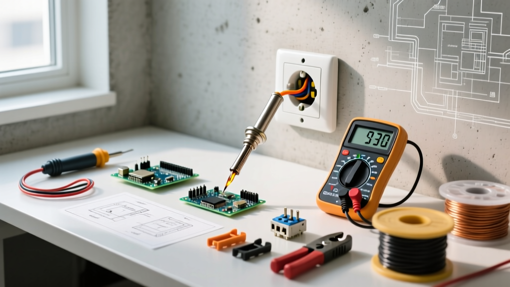
Essential Tools for Code-Compliant Repairs
To repair an outlet to professional and legal standards, you must move beyond basic hand tools. The 2023/2026 NEC introduced stricter torque verification requirements that demand specialized equipment.
| Tool Category | Recommended Model (2026) | Purpose & Code Relevance |
|---|---|---|
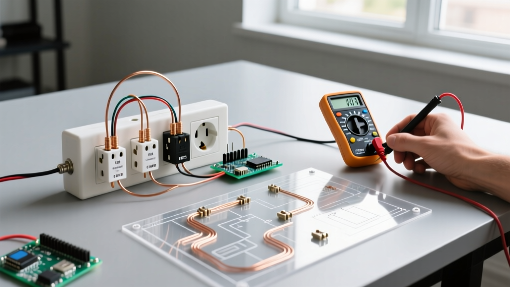
| Voltage Tester | Fluke 2AC II VoltAlert | Initial non-contact verification of de-energized state. |
| Digital Multimeter | Fluke 117 True-RMS (~$210) | Verifying zero potential (Line-Neutral, Line-Ground, Neutral-Ground). |
| Wire Stripper | Klein Tools 11055 | Precision stripping to 5/8' without nicking the copper conductor. |
| Torque Screwdriver | Wiha 320P or CDI 1002MFRMH | Required by NEC 110.14(D) to achieve exact terminal torque (typically 14 in-lbs). |
| Receptacle Tester | Gardner Bender GRT-300 | Post-repair verification of polarity, ground, and GFCI trip functionality. |
Step-by-Step Repair: How Do You Fix an Electrical Outlet Safely?
Follow this exact sequence to ensure maximum safety and code compliance. As outlined by OSHA Control of Hazardous Energy (Lockout/Tagout) guidelines, verifying a zero-energy state is non-negotiable.
- De-Energize and Lockout: Turn off the corresponding breaker at the main panel. Apply a physical lockout/tagout (LOTO) device to the breaker panel to prevent accidental re-energization while you are working.
- Verify Zero Energy: Remove the faceplate. Use your non-contact voltage tester, then confirm with a True-RMS multimeter. Measure Hot-to-Neutral, Hot-to-Ground, and Neutral-to-Ground. All readings must be 0.00V.
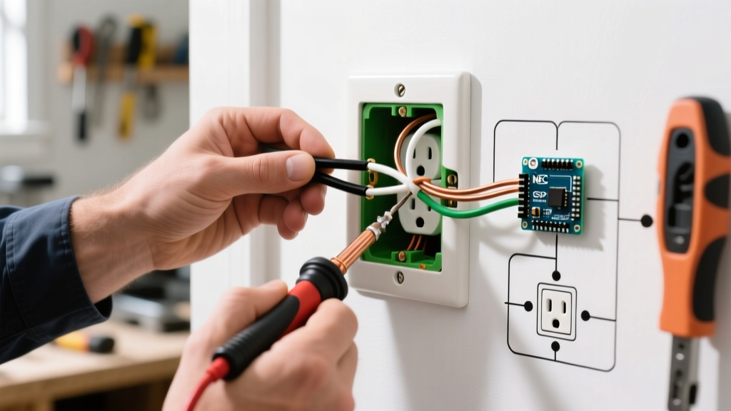
- Extract and Inspect: Unscrew the top and bottom mounting screws. Gently pull the receptacle out. Inspect the backbox for melted insulation, scorch marks, or crumbling wire coating. If the wire insulation is brittle and flakes off, the circuit has suffered thermal damage and requires professional rewiring.
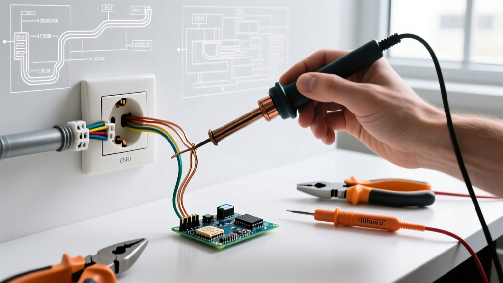
- Prepare the Conductors: If the wires were backstabbed, release them using a small flathead screwdriver. Never reuse backstabbed wire ends. Cut the wire back to fresh, undamaged copper. Using the Klein 11055, strip exactly 5/8-inch of insulation. This ensures no bare copper is exposed outside the terminal, and no insulation is trapped under the screw head.
- Terminate via Side-Wiring: Form a smooth 'J-hook' in the wire using needle-nose pliers. Hook the wire around the brass (hot) and silver (neutral) screws in a clockwise direction. This ensures that tightening the screw pulls the wire loop tighter rather than pushing it out.
- Apply Torque: Set your torque screwdriver to the manufacturer's specification (usually 14 in-lbs for standard 15A/20A Leviton or Hubbell receptacles). Tighten until the tool clicks. This prevents both loose connections (arc faults) and over-tightening (which shears the screw or deforms the brass plate).
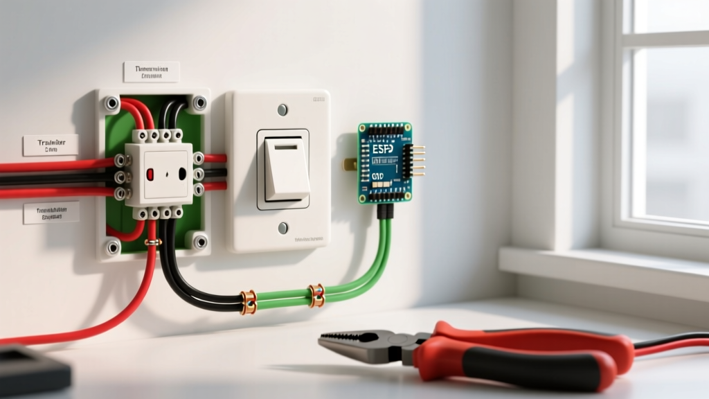
- Secure and Test: Push the wires neatly into the box using a folded accordion technique. Mount the receptacle, ensuring it is level and the yoke sits flush against the drywall or plaster ring. Re-energize and test with a plug-in receptacle tester.
2026 NEC Compliance Matrix for Receptacle Replacement
You cannot simply replace a broken receptacle with an identical legacy model. The U.S. Consumer Product Safety Commission (CPSC) and the NEC mandate that replacements must meet current safety codes for their specific location.
| Location / Application | Mandatory Receptacle Type | NEC Article Reference |
|---|---|---|
| All 15A & 20A, 125V Residential | Tamper-Resistant (TR) | 406.12 |
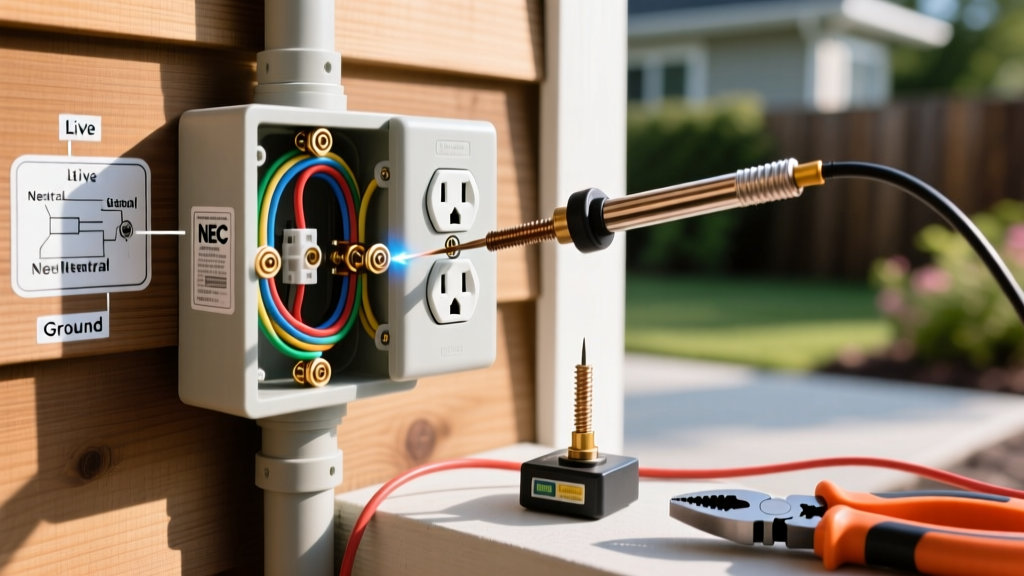
| Kitchens, Bathrooms, Garages, Outdoors | GFCI Protected (or GFCI Receptacle) | 210.8(A) |
| Bedrooms, Living Rooms, Hallways | AFCI Protected (via Breaker or Combo) | 210.12 |
| Kitchen Countertops | 20A Rated (Small Appliance Branch) | 210.52(B) |
| Bathrooms | 20A Rated, GFCI, No other loads | 210.11(C)(3) |
Code Alert: NEC 110.14(D) Torque Requirements
As of the 2023 NEC (widely enforced in 2026), 'Listed and identified equipment, such as receptacles, shall be installed such that the connections are made with a torque tool and set to the manufacturer's documented values.' Hand-tightening with a standard screwdriver is now a direct code violation in inspected jurisdictions.
Critical Edge Cases and Code Violations to Avoid
When troubleshooting how do you fix an electrical outlet, you will inevitably uncover legacy code violations left behind by previous owners or unlicensed handymen. Recognizing these is vital for your safety.
The 'Bootleg Ground' Hazard
In older homes with ungrounded (2-prong) wiring, a previous worker may have installed a modern 3-prong receptacle and placed a jumper wire between the neutral screw and the ground screw. This is known as a bootleg ground. It tricks receptacle testers into showing a 'correct' reading, but it is lethal. If a neutral fault occurs downstream, the metal casing of any plugged-in appliance will become energized at 120V. The Fix: Remove the jumper, replace the receptacle with a 2-prong model, or install a GFCI receptacle labeled 'No Equipment Ground' as permitted by NEC 406.4(D)(2).
Aluminum Branch Circuit Wiring
If you pull an outlet and discover dull, silver-colored wire instead of bright copper, you are dealing with aluminum wiring (common in homes built between 1965 and 1973). Aluminum expands and contracts at a different rate than brass terminals, leading to loosening and fires over time. The Fix: You must use a receptacle specifically marked CO/ALR (Copper/Aluminum Revised). Alternatively, and preferably, use AlumiConn lug connectors to pigtail the aluminum wire to a short copper whip, which then connects to a standard copper-rated TR receptacle.
Multi-Wire Branch Circuit (MWBC) Handle Ties
If you open a box and find two hot wires (usually one black, one red) connected to a single receptacle on different phases, this is an MWBC. If you are replacing the receptacle and need to break the hot-side tab to feed two separate circuits, NEC 210.4(B) requires that the breakers feeding this outlet be equipped with an identified handle tie or a 2-pole breaker to ensure simultaneous disconnection. Working on an MWBC without shutting off both poles can result in a fatal 240V shock from the shared neutral.
Final Verification and Drywall Repair
Once the outlet is wired, torqued, and tested, the final step is mechanical stability. A loose receptacle that wiggles when a plug is inserted will eventually degrade the terminal connections. If the gap between the drywall and the receptacle yoke exceeds 1/8-inch, NEC 314.20 requires the use of box extenders or rigid shims (like Caterpillar shims) to bridge the gap. Never use stacked, washable cardboard shims in damp locations, as they compress over time and compromise the fire-rating of the wall assembly.
By adhering to strict torque specifications, eliminating backstab connections, and enforcing modern TR and GFCI requirements, you ensure that your electrical repair is not just functional, but fundamentally safe for decades to come.