
Pre-Installation Circuit Inspection & Load Calculation
When planning to install an additional electrical outlet, the most common point of failure isn't the new receptacle itself—it's the upstream circuit overload. Before cutting into drywall or pulling new Romex, you must verify that the existing branch circuit has the thermal and amperage capacity to handle the new load. According to the National Fire Protection Association (NFPA) and current NEC adoption cycles, general lighting and receptacle circuits are calculated based on specific volt-ampere (VA) per square foot metrics, but practical load testing requires evaluating the existing continuous draw.
A standard 15-amp circuit (14 AWG copper) provides 1,800 watts of total capacity. However, the NEC 80% rule for continuous loads (those operating for 3 hours or more) restricts this to 1,440 watts. If you are adding an outlet to a home office or entertainment center, you must map the existing devices on that breaker using a plug-in watt meter (like the Kill A Watt P4460, typically $25-$30) before tying in the new line.
Circuit Capacity & Maximum Safe Load Matrix
| Circuit Breaker Size | Wire Gauge (Copper) | Total Max Wattage (120V) | Continuous Load Limit (80%) | Typical Outlet Configuration |
|---|---|---|---|---|
| 15 Amp | 14 AWG | 1,800W | 1,440W | NEMA 5-15R (Standard 2-slot/ground) |
| 20 Amp | 12 AWG | 2,400W | 1,920W | NEMA 5-20R (T-slot) or 5-15R |
| 20 Amp (Multi-Wire) | 12 AWG (x2 Hot, 1 Neutral) | 4,800W (Total) | 3,840W | Split receptacles or dedicated runs |
Pro Tip: Never add an additional electrical outlet to a 15-amp circuit that already services a bathroom, kitchen countertop, or laundry area. NEC Article 210.11(C) strictly requires these to be dedicated 20-amp small-appliance or laundry branch circuits with no other outlets outside their designated zones.
Inspecting the Existing Junction Box & Box Fill Rules
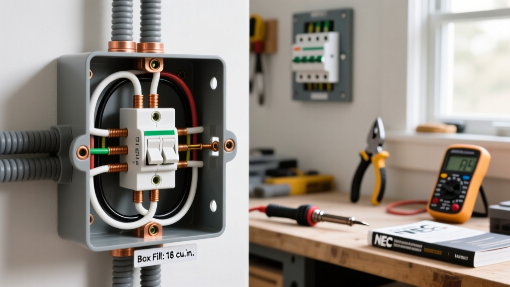
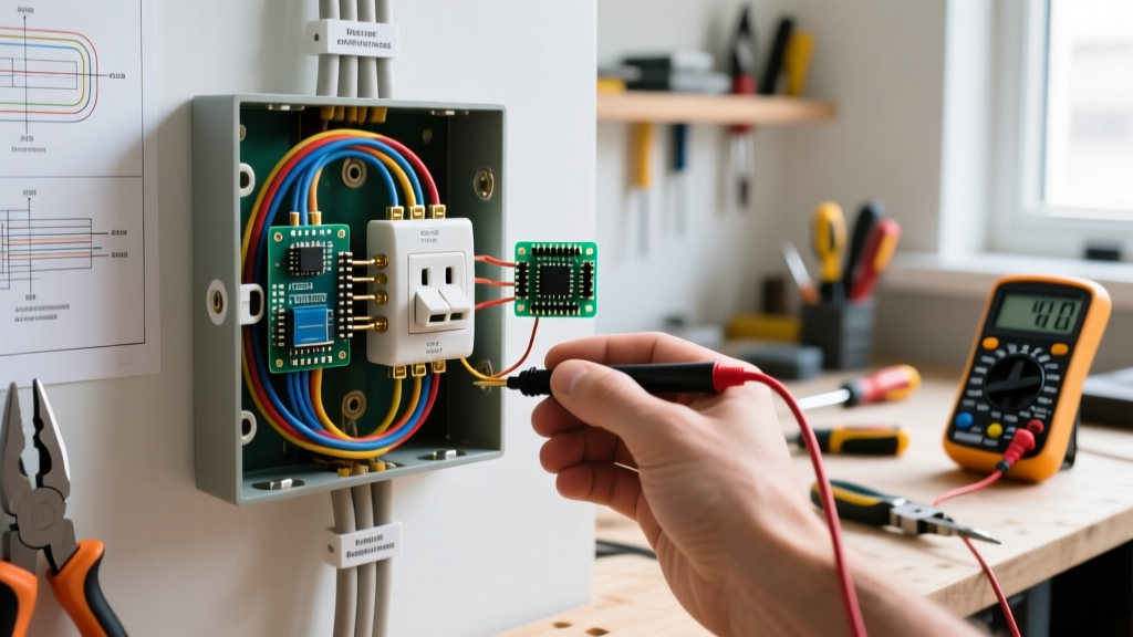
If you are piggybacking the new outlet off an existing receptacle box, you must perform a box fill calculation per NEC Article 314.16. Overcrowded boxes trap heat, degrading wire insulation and creating a severe fire hazard. Every wire, clamp, and device strap counts toward the cubic inch capacity of the box.
For 12 AWG wire, each current-carrying conductor requires 2.25 cubic inches of space. The grounding wires (all equipment grounds combined) count as a single conductor (2.25 cu in). The device (receptacle) counts as two conductors (4.5 cu in). Internal cable clamps count as one conductor (2.25 cu in).
- Example Scenario: You open an existing steel junction box (e.g., a Raco 8232, which is 2.5 cubic inches) to daisy-chain a new 12 AWG cable. The box already contains two 12 AWG cables (4 conductors + 1 ground) and one receptacle. The existing fill is already 13.5 cubic inches, vastly exceeding the box's 2.5 cu in rating. This is a severe code violation that must be corrected by upgrading to a deep 4x4 box (21 cu in) or an oversized retrofit box before adding the new line.
Wiring Verification & Torque Specifications
Modern electrical inspection heavily emphasizes termination torque. Loose connections cause arcing, which is the primary trigger for residential electrical fires. While many DIYers rely on the "tighten until snug" method, the 2023 NEC (widely enforced through 2026) references UL 486A/B standards, requiring terminations to be tightened to the manufacturer's specified torque.
Invest in an insulated torque screwdriver. The Klein Tools 60173 or Ideal Industries 35-850 (retailing between $110 and $140) are industry standards. For standard brass terminal screws on a 15A or 20A commercial-grade receptacle (like the Leviton ProGrade 5362), the required torque is typically:
- 14 AWG Solid Copper: 12 inch-pounds.
- 12 AWG Solid Copper: 16 inch-pounds.
- 10 AWG Solid Copper: 20 inch-pounds (rare for standard receptacles, common for 30A dryers/RVs).
Always wrap the wire clockwise around the terminal screw so that tightening the screw pulls the wire loop closed rather than pushing it out. Alternatively, use the back-wire clamp plates (not the push-in stab holes) found on higher-end spec-grade receptacles, which provide superior clamping force and require less physical clearance inside the junction box.
Post-Installation Testing: Verifying Your Additional Electrical Outlet
Once the wiring is complete and the drywall is patched, do not assume the outlet is safe simply because the breaker didn't trip. You must perform a systematic post-installation test. The Consumer Product Safety Commission (CPSC) emphasizes that visual inspection is insufficient; electronic verification is mandatory.
Step 1: Solenoid Voltage Tester Check
Before using sensitive digital electronics, use a solenoid voltage tester (often called a "Wiggy") or a non-contact voltage tester (NCVT) like the Fluke 1AC-II to confirm power is present at the hot slot (the shorter vertical slot). This provides a baseline confirmation that the breaker is successfully delivering voltage to the new node.
Step 2: Receptacle Analyzer Verification
Plug in a GFCI/AFCI receptacle tester, such as the Klein Tools RT210 (approx. $15). Read the LED matrix on the device:
- Correct Wiring: Two yellow/amber lights illuminated. Proceed to step 3.
- Open Ground: Only the left light is on. The equipment grounding conductor (EGC) is disconnected or broken upstream. This is highly dangerous and requires immediate correction.
- Reversed Polarity: The right and center lights are on. The hot and neutral wires are swapped at the terminal. This creates a shock hazard where the device's internal switch breaks the neutral instead of the hot.
- Hot/Ground Reverse: The left and right lights are on. This is a critical fault often caused by a miswired multi-wire branch circuit or a crossed wire in a junction box.
GFCI and AFCI Compliance Testing
Depending on the location of your additional electrical outlet, NEC Article 210.8 mandates Ground-Fault Circuit Interrupter (GFCI) protection for areas with water proximity (kitchens, bathrooms, garages, outdoors, unfinished basements), and Article 210.12 mandates Arc-Fault Circuit Interrupter (AFCI) protection for most living spaces (bedrooms, living rooms, hallways).
If you installed a standard receptacle downstream of an existing GFCI or on an AFCI breaker, you must test the upstream protection. Press the black "TEST" button on your RT210 or Gardner Bender GFI-3501 tester. This sends a simulated 6mA ground fault through the circuit. If the upstream breaker or GFCI receptacle does not immediately trip and cut power to your new outlet, the GFCI protection is either non-functional, improperly wired (line/load reversed), or missing entirely. For comprehensive arc-fault education, refer to the Electrical Safety Foundation International (ESFI) guidelines on AFCI compatibility with older appliances.
Common Failure Modes & Troubleshooting Edge Cases
Even with meticulous planning, adding an additional electrical outlet can reveal hidden legacy wiring issues. Below is a troubleshooting matrix for common post-installation anomalies.
| Symptom / Anomaly | Probable Cause | Diagnostic & Correction Strategy |
|---|---|---|
| Breaker trips instantly upon resetting | Dead short (Hot touching Ground/Neutral) or damaged cable sheathing inside the wall cavity. | Disconnect the new cable at the junction box. Reset breaker. If it holds, the fault is in the new run. Inspect for staple punctures or pinched Romex. |
| Outlet works, but voltage drops under load (e.g., vacuum cleaner bogs down) | High resistance connection, usually a loose back-stabbed wire upstream or undersized wire on a long run. | Measure voltage at the outlet under a 10A load. If it drops below 110V, trace upstream and convert all back-stabbed connections to screw-terminal or pigtail connections. |
| Neutral wire shows voltage when disconnected | Shared neutral (Multi-Wire Branch Circuit) with the other leg still energized. | Turn off BOTH breakers tied to the shared neutral before working. Verify 0V between neutral and ground with a multimeter. |
| GFCI tester fails to trip the upstream GFCI | Tester is on a circuit without a ground, or the GFCI "LOAD" terminals were not used for downstream protection. | Verify the new outlet is wired to the LOAD terminals of the upstream GFCI, not the LINE terminals. If no ground exists, a GFCI tester cannot function; test via the physical GFCI button instead. |
By adhering to strict load calculations, respecting box fill limitations, applying precise torque, and executing rigorous electronic testing, you ensure that your additional electrical outlet is not just functional, but fundamentally safe and fully compliant with modern electrical codes. Professional installation by a licensed electrician for a standard outlet addition typically ranges from $175 to $350 in 2026, factoring in drywall repair and circuit mapping. However, for the informed DIYer equipped with the right testing tools and NEC knowledge, it remains a highly manageable and rewarding upgrade.