
Initial Triage: Why Your Electric Outlet Has No Power
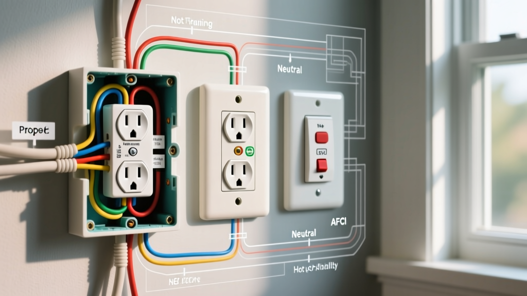
Encountering an electric outlet no power scenario is one of the most common residential electrical faults. Before tearing into the drywall or replacing the receptacle, a systematic diagnostic approach is required. In 2026, with the widespread adoption of smart breakers and advanced AFCI/GFCI protection, a dead receptacle is rarely just a 'bad outlet'—it is often a symptom of an upstream trip, a failed push-in connector, or a compromised neutral pigtail.
According to the National Fire Protection Association (NFPA), loose terminal connections are a leading cause of residential electrical fires. Therefore, diagnosing and repairing a dead outlet is not just about restoring convenience; it is a critical fire-prevention maintenance task.
The 3-Minute Diagnostic Checklist
- GFCI/AFCI Upstream Check: Test all GFCI receptacles in the same room and adjacent wet areas (kitchens, bathrooms, garages). A tripped GFCI upstream will cut power to standard downstream receptacles on the same circuit.
- Panel Verification: Check the main service panel. Look for breakers that are in the 'tripped' (center) position. AFCI breakers will often display a blinking LED or digital readout indicating the specific fault type (e.g., arc fault vs. ground fault).
- Load Test: Plug a known-working lamp into the dead outlet. If it flickers or fails to turn on, move to multimeter testing.
Essential Tools & Materials for 2026 Replacements
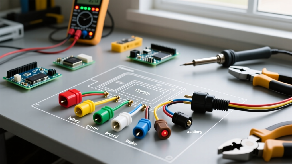
To properly diagnose and install a replacement, you must move beyond basic screwdrivers. Modern electrical codes demand precision and verified safety testing.
| Tool / Material | Specific Model Recommendation | Approx. 2026 Cost | Purpose |
|---|---|---|---|
| Non-Contact Voltage Tester | Fluke 1AC-II VoltAlert | $28 - $35 | Initial live circuit verification |
| Receptacle Tester | Klein Tools RT250 GFCI Tester | $45 - $55 | Verifying wiring topology and GFCI trip |
| Digital Multimeter | Fluke 117 True-RMS | $190 - $210 | Measuring exact line/load voltage drops |
| Torque Screwdriver | Wiha 320P (Set to 14 in-lbs) | $110 - $130 | NEC 110.14(D) compliant terminal tightening |
| Wire Connectors | Wago 221-413 Lever Nuts | $0.65 / each | Secure, vibration-proof pigtailing |
| Receptacle | Leviton 15A TR (R52-05320-00W) | $2.50 - $3.50 | Code-compliant Tamper-Resistant replacement |
Step-by-Step Diagnosis: Isolating the Dead Circuit
If the breaker is on and upstream GFCIs are reset, the fault lies within the outlet box or the immediate branch wiring. Follow these steps to isolate the failure mode.
Step 1: De-energize and Verify
Turn off the circuit breaker controlling the dead outlet. Insert your Fluke 1AC-II into the top and bottom slots of the receptacle. The absence of the red LED and audible alarm confirms the circuit is dead. Never skip this step, even if you believe you turned off the correct breaker.
Step 2: Extract and Inspect the Receptacle
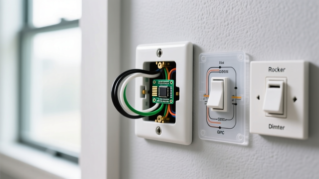
Remove the faceplate and the two mounting screws. Gently pull the receptacle out of the junction box. Do not touch any bare wires yet. Inspect the side of the device for thermal damage—look for melted nylon faceplates, black soot, or a distinct 'fishy' burning odor, which indicates severe arcing.
Step 3: Identify the Connection Type
Examine how the wires are terminated. If the wires are pushed into the back of the receptacle (backstabbed) rather than wrapped around the side terminal screws, you have likely found your culprit. Backstab connections rely on a small internal brass spring clip. Under heavy thermal cycling (like running a 12.5A space heater), these clips lose tension, leading to high resistance, arcing, and eventually, an open circuit resulting in an electric outlet with no power.
Data Matrix: Multimeter Readings & Failure Modes
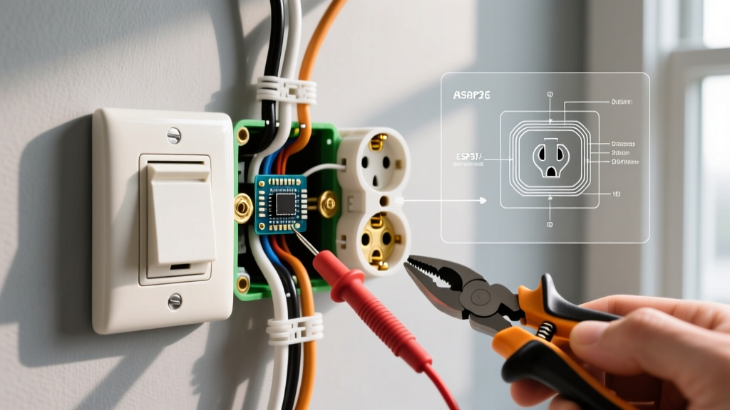
If the wiring looks intact, restore power temporarily to take voltage readings using your True-RMS multimeter. Set the dial to AC Voltage (V~).
| Probe Placement | Expected Reading | Actual Reading | Diagnosed Fault |
|---|---|---|---|
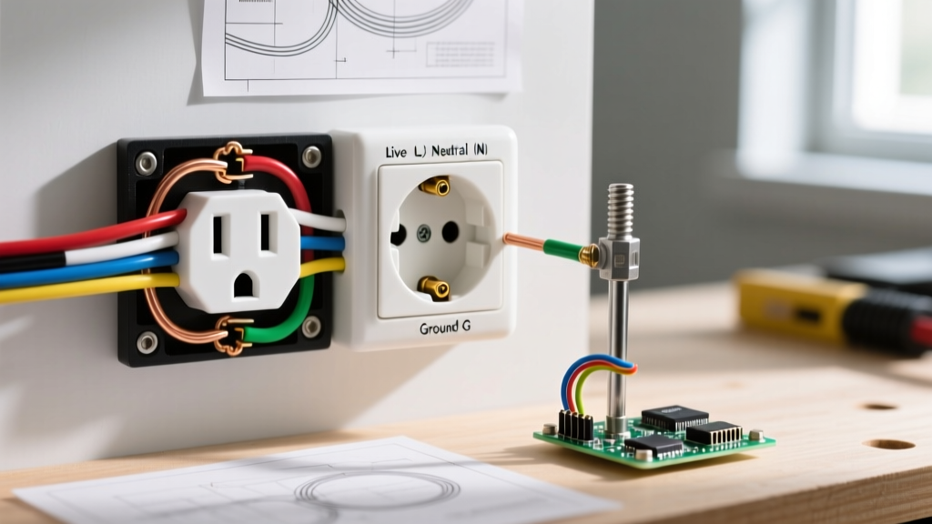
| Hot (Brass) to Neutral (Silver) | 120V AC | 0V AC | Open hot or open neutral; upstream disconnect. |
| Hot (Brass) to Ground (Green) | 120V AC | 120V AC | Neutral is open downstream of this point. |
| Hot (Brass) to Ground (Green) | 120V AC | 0V AC | Hot is open; breaker tripped or wire severed. |
| Neutral (Silver) to Ground (Green) | 0V - 2V AC | 120V AC | Reversed polarity or open neutral with load applied. |
Step-by-Step Installation: Replacing the Dead Receptacle
Once you have confirmed the receptacle is faulty or the backstab connections have failed, proceed with the installation of a new, code-compliant device.
Step 1: Disconnect and Prep Wires
With the power OFF, loosen the terminal screws or use a small flathead screwdriver to press the release slots next to the backstab holes to free the wires. Inspect the copper conductors. If the wire ends are pitted, blackened, or deeply grooved from previous arcing, use your Klein Tools 11055 wire strippers to cut back to clean copper. Strip exactly 3/4-inch of insulation for standard 14 AWG or 12 AWG solid copper wire.
Step 2: Form the J-Hook
Using the needle-nose pliers built into your wire strippers, form a tight 'J-hook' at the end of the conductor. The loop should be perfectly round so it sits flush under the terminal screw head without splaying out.
Step 3: Terminate on Side Screws (Never Backstab)
Hook the wire around the brass (hot) and silver (neutral) terminal screws in a clockwise direction. This ensures that as you tighten the screw, the loop pulls tighter rather than pushing out. Ensure no bare copper is exposed outside the terminal saddle, and no insulation is trapped under the screw head.
Expert Insight: As highlighted by OSHA electrical safety guidelines, improper terminations are a primary hazard in DIY electrical work. Always use side-wiring or screw-clamp plates. Abandon push-in backstab connectors entirely for high-reliability circuits.
Step 4: Torque to Specification
Modern NEC standards (specifically 110.14(D)) require terminals to be tightened to the manufacturer's specified torque. For a standard Leviton 15A/20A duplex receptacle, the side-wiring screws require 14 inch-pounds (in-lbs) of torque. Use a calibrated torque screwdriver. Overtightening can strip the brass threads or snap the screw; undertightening leads to thermal expansion gaps and future arcing.
Step 5: Pigtailing (If in the Middle of a Run)
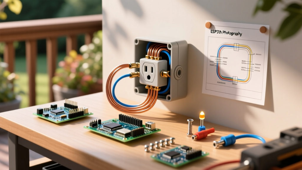
If your junction box contains two hot, two neutral, and two ground wires, this outlet is in the middle of a daisy chain. Do not use the receptacle itself to pass power downstream. Instead, use Wago 221-413 lever nuts to create pigtails. Connect the two line hots and one 6-inch black pigtail in a lever nut. Repeat for neutrals (white) and grounds (bare/green). Attach the single pigtail ends to the new receptacle. This ensures that if the receptacle is ever removed for painting or replacement, the downstream circuit remains intact.
Step 6: Box Makeup and Final Test
Carefully fold the wires into the back of the junction box. Push the neutral wires to the back, followed by the grounds, and finally the hots. Mount the new Tamper-Resistant (TR) receptacle using the provided mounting screws, ensuring the yoke sits flush against the drywall or plaster ring. Install the faceplate, restore power at the breaker, and test with your Klein RT250 receptacle tester to verify correct wiring and GFCI functionality.
Code Compliance & Safety Upgrades for 2026
When replacing a dead outlet, you must adhere to current local codes, which generally follow the latest NEC adoption cycle.
- Tamper-Resistant (TR) Mandate: All 15A and 20A, 125V and 250V receptacles in dwelling units must be TR type. These feature internal spring-loaded shutters that prevent children from inserting foreign objects. Standard non-TR receptacles are illegal for new replacements in living spaces.
- AFCI Protection: If the dead outlet is in a bedroom, living room, or hallway, the circuit must be AFCI protected. If your panel lacks an AFCI breaker, you must either upgrade the breaker or install an AFCI receptacle at the first outlet in the branch circuit.
- GFCI Protection: Outlets in kitchens, bathrooms, garages, outdoors, and within 6 feet of a sink require GFCI protection. If replacing a dead GFCI outlet, ensure you connect the incoming power to the LINE terminals and downstream outlets to the LOAD terminals. Reversing these will leave the GFCI functional but strip protection from downstream devices.
For comprehensive residential safety standards, always consult the Consumer Product Safety Commission (CPSC) home electrical safety guidelines before undertaking panel or branch circuit modifications.
FAQ: Edge Cases in Dead Outlet Troubleshooting
Why does my outlet have 120V but won't power my lamp?
This is a classic 'open neutral under load' or 'high-resistance connection' ghost voltage issue. A digital multimeter has high impedance and can read 120V across a broken wire that is merely capacitively coupled to a live wire. When you plug in a lamp (a real load), the voltage drops to zero. Check for a broken neutral wire or a failed backstab connection upstream.
Can a bad outlet trip the main breaker?
Yes. If the internal brass contacts inside the receptacle degrade and touch, or if the hot wire's insulation melts and contacts the grounded metal junction box, it will create a dead short. This will instantly trip the breaker or blow the fuse. If your breaker trips immediately upon resetting, do not force it; the fault must be isolated and repaired.