
Diagnosing and Repairing a Dead Receptacle: The Complete Beginner's Guide
A dead electrical outlet is one of the most common household electrical issues, but it is rarely a mystery. In most cases, the failure stems from a tripped upstream GFCI, a loose backstabbed wire, or a worn-out internal brass contact. Learning how to fix electrical outlet connections safely requires a methodical approach, an understanding of 120V circuit fundamentals, and strict adherence to safety protocols.
This tutorial walks you through diagnosing the root cause, safely removing the faulty unit, and installing a modern, code-compliant replacement. We will focus on standard 15-amp, 120-volt duplex receptacles found in living rooms, bedrooms, and hallways.
Safety Warning: Never attempt to work on an electrical outlet without first verifying that the circuit is de-energized at the breaker panel. According to the Electrical Safety Foundation International (ESFI), arc flashes and severe shocks occur when DIYers rely solely on wall switches or assume a breaker is correctly labeled. Always test before you touch.
Phase 1: Diagnostic Troubleshooting (Before You Unscrew Anything)
Before pulling out your screwdriver, determine if the outlet actually requires physical replacement or if the issue lies elsewhere in the circuit.
1. Check for Upstream GFCI Trips
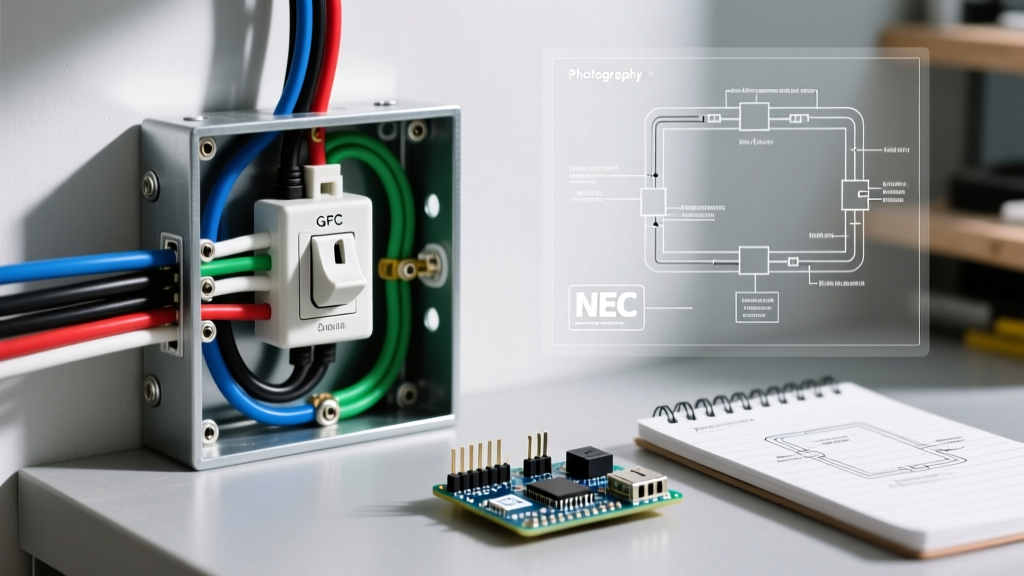
Standard outlets in bedrooms or living rooms are often wired on the 'load' side of a GFCI (Ground Fault Circuit Interrupter) receptacle located in a nearby bathroom, garage, or exterior wall. If the upstream GFCI trips, all downstream standard outlets will lose power. Locate all GFCI outlets in your home and press the 'Reset' button.
2. Verify the Circuit Breaker
Check your main electrical panel. A tripped breaker will sit in a middle position between ON and OFF. To reset it, push the breaker firmly to the OFF position until it clicks, then flip it back to ON. If it immediately trips again, you have a short circuit or ground fault—do not force it on, and call a licensed electrician.
3. Test for 'Backstab' Failure
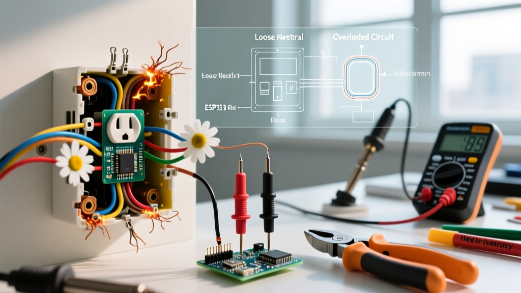
If the breaker is on and no GFCI is tripped, the issue is likely at the outlet itself. Builders frequently use 'backstabbed' push-in connections to save time. Over years of thermal expansion and contraction from plugging and unplugging devices, the internal spring tension weakens, causing the wire to lose contact. This is the number one cause of intermittent or dead outlets.
Required Tools and Materials
Do not rely on cheap, uncalibrated testers. Invest in reliable diagnostic tools to ensure your safety and the longevity of your repair.
- Non-Contact Voltage Tester: Fluke 1AC-II VoltAlert (~$25). Do not use budget pens; they can yield false negatives on shielded cables.
- Receptacle Tester: Klein Tools RT250 (~$20) to verify wiring correctness post-installation.
- Screwdrivers: Klein Tools 11-in-1 Multi-Tool (~$20) with Phillips #2 and Flathead tips.
- Wire Strippers: Ideal Industries Reflex T-Stripper (calibrated for 14 AWG and 12 AWG solid copper).
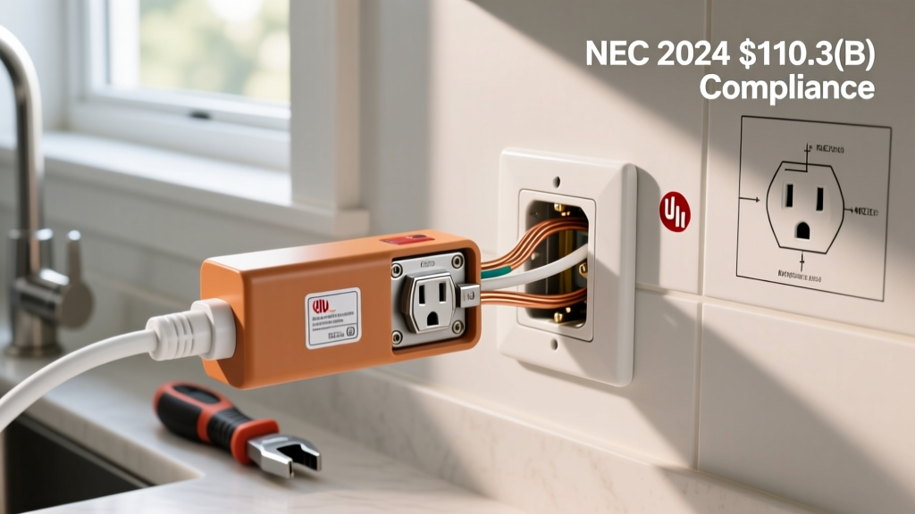
- Replacement Receptacle: Leviton T53-25W 15-Amp Tamper-Resistant (TR) Duplex Receptacle (~$3.50). The National Electrical Code (NEC) mandates TR receptacles in all dwelling units to prevent childhood injuries.
Step-by-Step Outlet Replacement Procedure
Step 1: Kill the Power and Verify
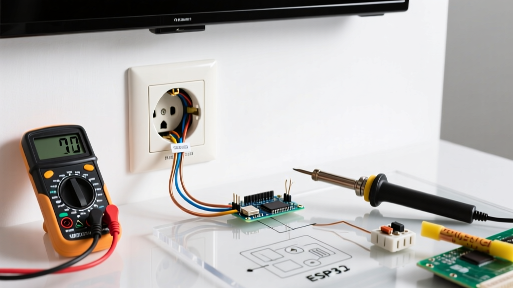
Turn off the circuit breaker controlling the outlet. Plug a lamp into the receptacle to confirm it is dead. Next, insert your Fluke non-contact voltage tester into both slots of the top and bottom receptacles. The tester must remain completely dark and silent. If it beeps or glows, you have turned off the wrong breaker.
Step 2: Extract the Faulty Receptacle
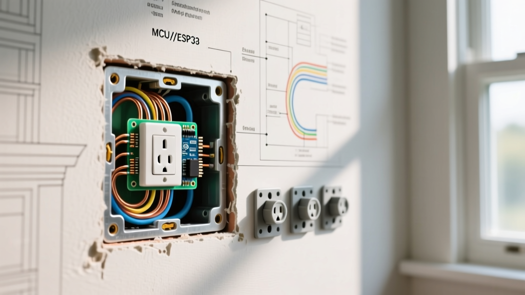
Remove the single center screw on the faceplate. Remove the top and bottom mounting screws securing the outlet to the junction box. Gently pull the outlet out, being careful not to yank the wires. Note the wire placement before disconnecting anything. Take a photo with your smartphone for reference.
Step 3: Inspect and Prepare the Wiring
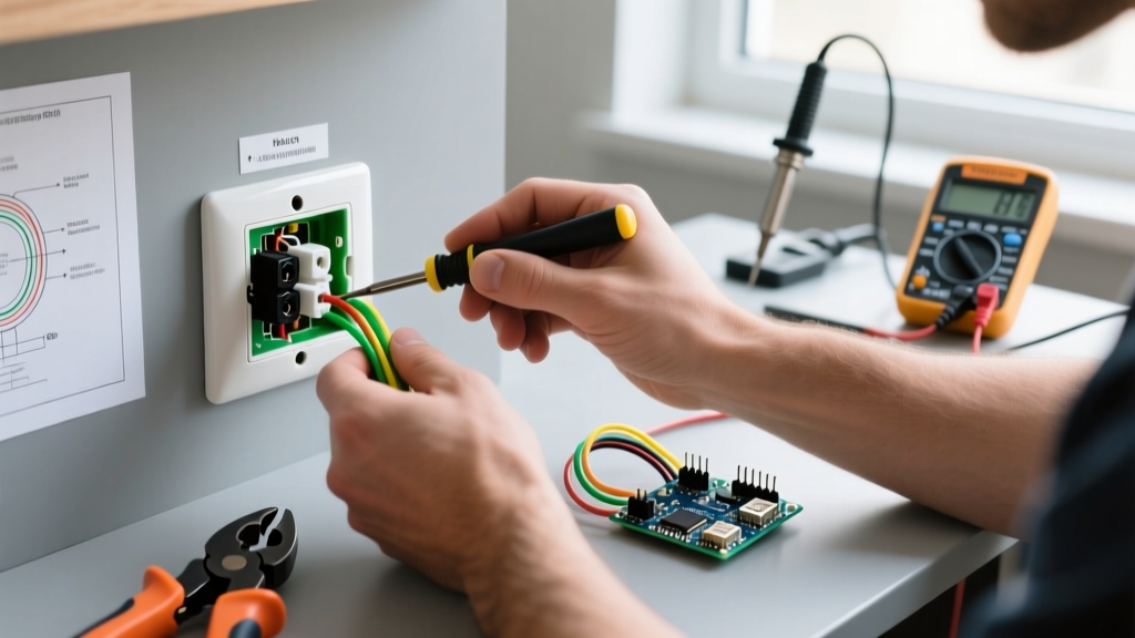
Disconnect the wires. If they were backstabbed, use a small flathead screwdriver to press the release slot next to the wire hole, or simply snip the wire close to the back of the outlet with your wire strippers.
Inspect the exposed copper. If it is heavily oxidized, blackened, or deeply grooved from previous screw terminals, snip it back to fresh copper. Use your wire strippers to strip exactly 3/4 of an inch of insulation. Use the strip gauge molded into the back of your new Leviton receptacle to verify the length. Exposed copper beyond the terminal screw creates a shock hazard; too little copper causes the screw to bite into the insulation, leading to a high-resistance connection and potential fire.
Step 4: Terminate Using Side Screws or Clamp Plates
Never use the push-in backstab holes on the new receptacle. Instead, use the side screw terminals or the screw-down clamp plates located on the sides of the device.
Create a 'J-hook' in the bare copper wire using the nose of your pliers. Hook the wire around the terminal screw in a clockwise direction. This ensures that as you tighten the screw, the loop closes tighter rather than being pushed out from under the screw head.
- Brass Screws (Hot): Connect the black (or red) wire.
- Silver Screws (Neutral): Connect the white wire.
- Green Screw (Ground): Connect the bare copper or green wire.
Step 5: Torque the Terminals
The NEC (Article 110.14(D)) requires electrical connections to be torqued to the manufacturer's specifications. For a standard Leviton 15A receptacle, the required torque is typically 12 to 14 inch-pounds. While professional electricians use calibrated torque screwdrivers (like the Klein Tools 32500TORQ), a beginner can achieve a safe connection by tightening the screw until it is snug, then giving it an additional quarter-turn with a standard screwdriver. Do not overtighten, as this can strip the brass threads.
Step 6: Secure and Test
Carefully fold the wires back into the junction box in a 'Z' pattern (ground first, then neutrals, then hots). Align the receptacle and tighten the mounting screws. Ensure the yoke (the metal strap) sits flush against the drywall or plaster. If the box is recessed, use plastic outlet shims (cat. no. P700W) to prevent the outlet from flexing when devices are plugged in. Restore power at the breaker and test with your Klein RT250 receptacle tester to confirm correct wiring.
Common Outlet Failure Modes and Symptoms
Understanding why an outlet fails helps you identify edge cases during your repair. The National Fire Protection Association (NFPA) notes that poor connections are a leading cause of residential electrical fires.
| Symptom | Probable Root Cause | Required Action |
|---|---|---|
| Outlet is dead; adjacent outlets work. | Upstream GFCI tripped or backstabbed wire disconnected. | Reset GFCI or replace outlet using side-screw terminals. |
| Visible sparks when plugging in a device. | Internal brass contact fatigue or loose hot wire. | Replace receptacle immediately; inspect wire termination. |
| Brown burn marks on the plastic faceplate. | High-resistance connection causing arcing and heat. | Replace outlet, strip wire to fresh copper, and torque properly. |
| Half of the outlet is always hot, half is switched. | Split-receptacle wiring; brass side break-off tab removed. | Ensure the brass fin is broken off on the new outlet to match. |
Expert Insight: Pigtailing vs. Daisy Chaining
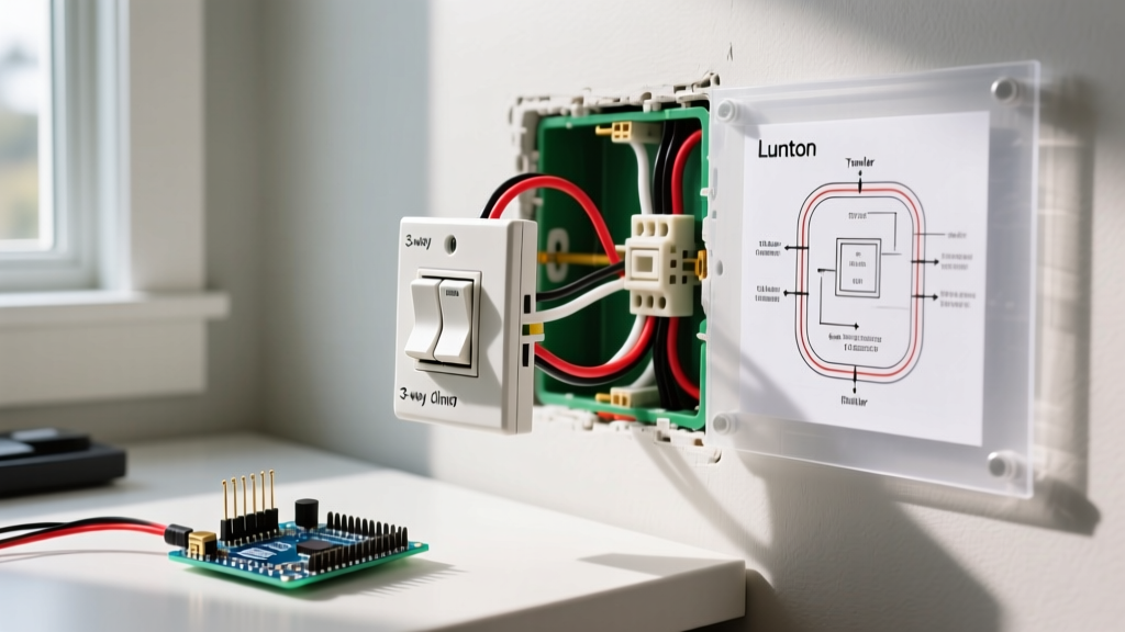
When you open the junction box, you may see multiple cables (e.g., two black wires, two white wires). This indicates the outlet is 'daisy-chained,' passing power to the next outlet in the circuit.
The Beginner Mistake: Connecting both black wires to the single brass screw on the receptacle, or using both the side screw and the backstab hole for the same circuit. This places the entire downstream load on the outlet's internal brass strap.
The Professional Method (Pigtailing): Use a wire nut (or Wago 221 lever connector) to join the incoming hot, the outgoing hot, and a short 6-inch piece of black wire (the 'pigtail'). Connect only the single pigtail to the brass screw on the receptacle. This ensures that if the outlet fails or is removed in the future, the downstream outlets will not lose power. The Consumer Product Safety Commission (CPSC) strongly advocates for secure, permanent splicing methods to prevent arcing faults in residential wiring.
Final Thoughts on Code Compliance
Fixing an electrical outlet is a highly manageable DIY project when you respect the physics of the circuit and prioritize termination quality over speed. By abandoning backstab connections, stripping wires to the exact 3/4-inch gauge, and ensuring firm mechanical torque, your repaired outlet will provide decades of safe, reliable service. Always remember: if your junction box lacks a ground wire (common in pre-1960s homes), you must either install a GFCI receptacle labeled 'No Equipment Ground' or hire an electrician to run a new grounded circuit.