
The Essential Diagnostic Toolkit for Outlet Troubleshooting
Diagnosing faults across different electrical outlet types requires more than just a basic plug-in tester. As residential and commercial electrical systems evolve to meet 2026 energy demands and updated NEC (National Electrical Code) safety standards, the internal architecture of receptacles has become increasingly complex. To accurately troubleshoot these devices, you need precision instruments.
- True-RMS Digital Multimeter: The Fluke 117 or Klein Tools MM400 is essential for measuring exact AC voltage and detecting phantom voltages in AFCI circuits.
- GFCI/AFCI Receptacle Tester: The Klein RT210 or Gardner Bender GFI-3501 can simulate ground faults and arc faults to verify internal trip mechanisms.
- Torque Screwdriver: NEC 110.14(D) mandates specific torque values for wire terminations. A calibrated tool like the Klein 32500 ensures connections are tightened to the manufacturer's spec (typically 12 to 14 in-lbs for standard 15A/20A devices).
- Thermal Imaging Camera: Devices like the FLIR C5 help identify thermal creep and high-resistance connections hidden behind the wall plate.
Standard 15A and 20A Duplex Receptacles (NEMA 5-15R & 5-20R)
The standard duplex receptacle remains the most common outlet in North America. However, its simplicity often masks severe installation errors that lead to intermittent power loss or fire hazards.
Common Failure Modes
- Backstab (Push-In) Connection Failures: Builder-grade receptacles often feature spring-loaded push-in terminals. Over time, thermal expansion and contraction cause the internal brass springs to lose tension, resulting in high-resistance connections. This manifests as voltage drops under load or melted plastic faces.
- Loose Neutral Wire: If the white neutral wire is loose, devices plugged into the outlet may experience overvoltage or undervoltage, especially on multi-wire branch circuits (MWBC), potentially destroying sensitive electronics.
- Daisy-Chaining Degradation: When outlets are wired in series (line and load on the same device), a single loose connection can kill power to all downstream receptacles.
Diagnostic Protocol
Remove the wall plate and inspect the side wire terminals. If wires are pushed into the back, immediately remove them and terminate them under the side screw terminals. Use your multimeter to measure voltage between the hot (brass) and neutral (silver) screws. A reading below 115V under a 10A dummy load indicates a high-resistance joint upstream.
GFCI (Ground Fault Circuit Interrupter) Outlets
GFCI receptacles contain an internal current transformer that monitors the balance between the hot and neutral conductors. If an imbalance of just 4 to 6 milliamps is detected, an internal shunt trip mechanism cuts the power in milliseconds. According to the U.S. Consumer Product Safety Commission, GFCIs have prevented thousands of electrocutions since their mandate in wet locations.
Decoding GFCI LED Indicators
Modern GFCIs feature End-of-Life (EOL) lockout technology. If the internal diagnostic circuit fails, the outlet permanently disables itself. Below is a diagnostic matrix based on industry-standard Leviton SmartLock Pro receptacles:
| LED Status | Meaning | Troubleshooting Action |
|---|---|---|
| Solid Green | Device is functioning normally. | No action required. |
| Solid Red | Internal fault detected or EOL reached. | Replace the GFCI immediately; it cannot be reset. |
| Off (No Light) | Device is tripped or line/load reversed. | Press TEST then RESET. If it fails, verify wiring polarity. |
| Flashing Red | Self-test failure upon power-up. | Replace the receptacle. |
The 'Phantom Trip' Diagnosis
If a GFCI trips without a ground fault present, check for downstream moisture ingress in outdoor junction boxes or failing appliance capacitors. Induction motors (like older sump pumps) can generate electrical noise that mimics a ground fault, causing nuisance tripping.
AFCI (Arc Fault Circuit Interrupter) Receptacles
AFCI outlets detect dangerous parallel and series arcing conditions that standard breakers miss. Troubleshooting AFCIs is notoriously difficult because they react to high-frequency electrical noise.
Nuisance Tripping Causes
- Shared Neutrals: If the neutral wire from an AFCI-protected circuit is accidentally spliced with a neutral from a standard circuit in a junction box, the AFCI will detect an imbalance and trip immediately upon load.
- Motor Brushes: Vacuum cleaners, power drills, and older HVAC blower motors generate natural arcing at the carbon brushes. While modern 2026 AFCI algorithms are better at filtering this, aging motors can still trigger false positives.
- Dimmer Switch Interference: Incompatible LED drivers on shared circuits can inject harmonic distortion back into the panel, confusing the AFCI microprocessor.
Pro Tip: Use an oscilloscope or a high-end power quality analyzer to view the waveform if an AFCI refuses to stay reset. You are looking for high-frequency transients exceeding the manufacturer's trip curve.
High-Voltage 240V Outlets (NEMA 14-50R & 6-50R)
With the massive surge in residential EV charging, the NEMA 14-50R (50A, 125/250V) has become a critical diagnostic focal point. Continuous EV charging loads push these receptacles to their absolute thermal limits.
Thermal Failure and Lug Melting
Standard residential-grade NEMA 14-50 receptacles are not designed for continuous 40A draws (80% of the 50A rating) over 8 to 12 hours. The internal brass contacts expand, lose grip on the plug blades, and create massive resistance. This results in melted neutral lugs and scorched faceplates. The National Fire Protection Association (NFPA) emphasizes strict adherence to continuous load calculations in the NEC to prevent these thermal events.
The Upgrade Solution
If you are diagnosing a melted NEMA 14-50R, do not replace it with another cheap residential model. Upgrade to an industrial-grade receptacle like the Hubbell 9450FR or Bryant 9450FR. These feature heavy-duty glass-reinforced nylon bodies and high-tension nickel-plated brass contacts that easily handle continuous EV charging without thermal degradation.
Integrated USB and Smart Wi-Fi Outlets
Outlets with built-in USB-A/USB-C ports and Wi-Fi/Zigbee smart modules introduce DC power supplies directly into the AC junction box.
Diagnosing DC Transformer Burnout
When the USB ports stop charging but the AC duplex remains functional, the internal step-down transformer or switching power supply has failed. This is usually caused by cheap electrolytic capacitors bulging due to heat trapped inside a crowded wall box. Because these components are potted in resin or integrated into the PCB, they cannot be repaired. The entire receptacle must be replaced.
Smart Outlet Wi-Fi Dropouts
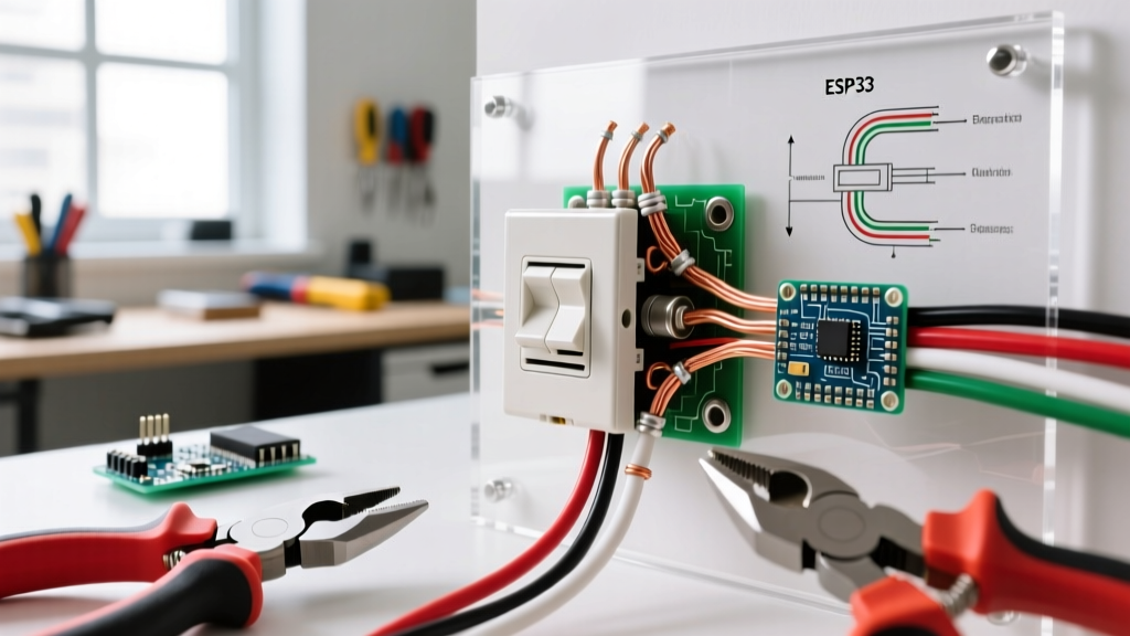
Smart outlets require a constant 2.4GHz Wi-Fi signal and a dedicated neutral wire. If the outlet frequently drops offline, verify the neutral connection is tight. A loose neutral causes voltage sags that reboot the internal ESP32 or Wi-Fi microcontroller, putting it into an endless boot loop.
Step-by-Step Voltage Drop Testing
To definitively diagnose a failing outlet under load, perform a voltage drop test:
- Plug a high-wattage resistive load (like a 1500W space heater) into the suspect outlet.
- Measure the AC voltage directly at the receptacle's hot and neutral slots using your True-RMS multimeter.
- Walk to the main electrical panel and measure the voltage at the corresponding breaker terminal.
- Calculate the difference. According to NEC recommendations, the voltage drop on a branch circuit should not exceed 3% (roughly 3.6V on a 120V circuit). A drop greater than 5% indicates severe wire degradation, undersized conductors, or a failing connection upstream.
Safety Warning: Always de-energize the circuit at the main breaker panel before removing any receptacle from the wall box. Use a non-contact voltage tester (NCVT) and a multimeter to verify zero energy state. If you encounter aluminum wiring, double-tapped breakers, or signs of active arcing (black soot and ozone smell), halt diagnostics and contact a licensed electrical contractor immediately.
Understanding the unique failure modes of different electrical outlet types transforms troubleshooting from a guessing game into a precise, data-driven science. By leveraging the right diagnostic tools and respecting the thermal limits of modern electrical components, you can ensure a safe, reliable power distribution system in any home or facility. For deeper specifications on receptacle configurations, consult the official Leviton GFCI technical documentation or your local authority having jurisdiction (AHJ).