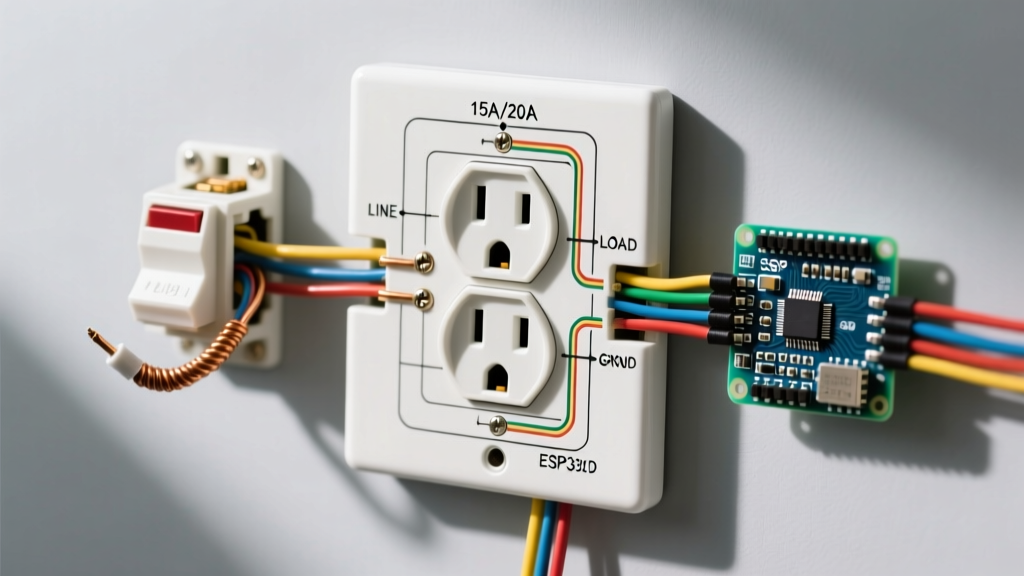

Demystifying the Electrical Wall Outlet Wiring Diagram
For a beginner, staring at an electrical wall outlet wiring diagram can feel like trying to read a foreign language. You see a maze of black, white, and bare copper lines intersecting with brass, silver, and green terminals. However, understanding these schematics is the foundational skill for any safe DIY electrical project. Whether you are replacing a damaged standard duplex receptacle or installing a new GFCI (Ground Fault Circuit Interrupter) in your kitchen, the diagram is your roadmap to preventing short circuits, electrical fires, and failed inspections.
In this comprehensive beginner tutorial, we will break down the most common residential outlet diagrams, explain the critical differences between LINE and LOAD, and provide exact torque specifications and tool requirements aligned with the latest 2026 National Electrical Code (NEC) standards.
Decoding the Standard 15A and 20A Duplex Receptacle Diagram
The standard 125-volt duplex receptacle (commonly a Leviton 5262-SW for 15A or 5362-SW for 20A) features a straightforward physical layout that directly correlates to its wiring diagram. The diagram will always show three primary termination points. Understanding the color-coding and physical placement of these screws is step one.
Terminal Mapping and Wire Identification
Unlike complex smart switches, a standard outlet does not require a neutral wire to be daisy-chained through the device itself; it simply terminates there. Here is the exact mapping you will see on any standard electrical wall outlet wiring diagram:
- Brass Screws (Hot): Connects to the black (or sometimes red) insulated wire. This carries the 120V current from your breaker panel.
- Silver Screws (Neutral): Connects to the white insulated wire. This completes the circuit, returning current to the panel.
- Green Screw (Ground): Connects to the bare copper or green insulated wire. This provides a safe path for fault currents, tripping the breaker in the event of a short.
| Terminal Type | Wire Color | Wire Gauge (AWG) | Required Torque (in-lbs) | Screw Head Type |
|---|---|---|---|---|
| Brass (Hot) | Black / Red | 14 AWG | 12 in-lbs | Slotted / Phillips |
| Brass (Hot) | Black / Red | 12 AWG | 14 in-lbs | Slotted / Phillips |
| Silver (Neutral) | White | 14 AWG | 12 in-lbs | Slotted / Phillips |
| Silver (Neutral) | White | 12 AWG | 14 in-lbs | Slotted / Phillips |
| Green (Ground) | Bare / Green | 14 or 12 AWG | 12 in-lbs | Slotted / Hex |
Step-by-Step: Wiring a Standard Outlet from the Diagram
Reading the diagram is only half the battle; executing the physical wiring requires precision. According to the U.S. Consumer Product Safety Commission (CPSC), loose connections are a leading cause of residential electrical fires. Follow these exact steps to match your physical installation to the diagram.
- Verify Power is Off: Use a non-contact voltage tester (like the Klein Tools NCVT-3, approx. $35) on the existing outlet. Test a known live circuit first to ensure the tester's battery is functioning.
- Strip the Wires Correctly: Use the built-in strip gauge on the back of the receptacle. For most modern Leviton and Eaton devices, this is exactly 5/8 of an inch. Stripping too much leaves exposed copper (a shock hazard); stripping too little causes the screw to bite into the wire insulation, leading to a high-resistance connection and eventual melting.
- Form the J-Hook: Using needle-nose pliers, bend the stripped copper into a 'J' shape or shepherd's hook.
- Loop Clockwise: Place the hook around the terminal screw so that it loops clockwise. When you tighten the screw (clockwise), the hook will pull tighter around the screw shaft. If looped counter-clockwise, tightening the screw will push the wire out.
- Torque to Specification: Use a calibrated torque screwdriver (such as the Klein Tools 11907). NEC 110.14(D) strictly mandates that terminations be torqued to the manufacturer's specifications. Hand-tightening is no longer code-compliant for new installations.
The GFCI Outlet Wiring Diagram: LINE vs. LOAD Explained
The most confusing electrical wall outlet wiring diagram for beginners is the GFCI receptacle. Unlike standard outlets, GFCIs (required in kitchens, bathrooms, garages, and outdoors per NFPA NEC Article 210.8) feature two distinct sets of terminals: LINE and LOAD.
Critical Safety Warning: Connecting the incoming power to the LOAD terminals instead of the LINE terminals is the #1 beginner mistake. If wired backward, the GFCI will still power the outlet, but the internal ground-fault protection mechanism will be completely disabled, leaving you unprotected from lethal shocks.
How to Identify LINE and LOAD
- LINE Terminals: These connect to the wires bringing power from the breaker panel. If you only have one cable entering the box, it always connects to LINE.
- LOAD Terminals: These connect to wires carrying power downstream to protect additional standard outlets on the same circuit. If you have two cables in the box, use a voltage tester to identify which cable is hot before touching any wires. The hot cable goes to LINE; the downstream cable goes to LOAD.
Modern GFCI diagrams (like those for the Leviton SmartlockPro series) clearly mark LINE with yellow tape or labeling and LOAD with black tape or labeling. Always follow the manufacturer's specific diagram included in the box, as terminal placements can vary slightly between brands like Eaton, Legrand, and Leviton.
Split-Wired (Half-Hot) Receptacle Diagrams
A split-wired diagram shows a single duplex outlet where the top half is controlled by a wall switch (often for a lamp), and the bottom half remains constantly hot. This requires a 3-wire cable (e.g., 14/3 or 12/3 Romex) containing a black wire, a red wire, a white neutral, and a bare ground.
The Brass Tab Break
To achieve this, the wiring diagram will show a physical modification to the receptacle: breaking the connecting tab on the brass (hot) side only. Using diagonal cutters, snap the small brass fin between the top and bottom brass screws. This isolates the two halves of the outlet. The black wire connects to the bottom brass screw (constant hot), and the red wire connects to the top brass screw (switched hot). The silver (neutral) tab must never be broken in this scenario, as both halves share the same white neutral wire.
Common Diagram Misinterpretations and Failures
Even when you think you understand the electrical wall outlet wiring diagram, execution errors can occur. Watch out for these specific failure modes:
1. Backstabbing vs. Side Wiring
Many diagrams show wires wrapping around screws (side wiring), but the physical outlet also has push-in holes on the back (backstabbing). Never use backstab connections. They rely on a tiny internal spring clip that grips the wire. Over time, thermal expansion and contraction from electrical loads cause these clips to loosen, creating arc faults. Always use the side terminal screws or, if multiple wires need to connect, use a pigtail with a WAGO 221-413 lever nut.
2. Reversed Polarity
If you accidentally swap the black (hot) and white (neutral) wires, the outlet will still function, and a lamp will turn on. However, the internal wiring of the appliance will remain energized even when the appliance's switch is turned off. This is a severe shock hazard. Always verify your work with a $15 receptacle tester (like the Gardner Bender GRT-501) which uses LED light patterns to confirm correct polarity and ground presence.
3. Bootleg Grounds
In older homes with ungrounded 2-prong wiring, some beginners attempt to fake a ground by connecting a jumper wire from the neutral silver screw to the green ground screw. This is known as a 'bootleg ground.' It is highly illegal, incredibly dangerous, and will cause the metal chassis of any plugged-in appliance to become energized with 120V if the neutral wire ever fails upstream. If you have no ground wire, the NEC allows you to install a GFCI receptacle and label it 'No Equipment Ground,' which provides shock protection without a physical ground wire.
Essential Tools and 2026 Material Costs
To properly execute any outlet wiring diagram, you need the right tools. Budget for the following essentials to ensure a code-compliant, safe installation:
| Tool / Material | Recommended Model | Approx. 2026 Cost | Purpose |
|---|---|---|---|
| Non-Contact Voltage Tester | Klein Tools NCVT-3 | $35.00 | Verifying power is off before touching wires. |
| Torque Screwdriver | Klein Tools 11907 (or Wiha 320P) | $110.00 - $140.00 | Meeting NEC 110.14(D) terminal torque specs. |
| Wire Strippers | Klein Tools 11055 (10-20 AWG) | $28.00 | Stripping exactly 5/8' of insulation without nicking copper. |
| Receptacle Tester | Gardner Bender GRT-501 | $14.00 | Testing for open grounds, reversed polarity, and GFCI trip. |
| Lever Nuts (Pigtailing) | WAGO 221-413 (3-conductor) | $0.75 / each | Safe, reusable splicing when daisy-chaining outlets. |
| 15A TR Receptacle | Leviton 5262-SW (Tamper Resistant) | $2.50 - $3.50 | Standard code-compliant replacement outlet. |
Final Safety and Code Reminders
Before closing up the electrical box and turning the breaker back on, perform a final visual inspection against your electrical wall outlet wiring diagram. Ensure no bare copper is visible outside the terminal connections, verify that the ground wire is firmly seated, and confirm that the receptacle is sitting flush against the drywall without being over-tightened (which can crack the plastic yoke). For further reading on residential electrical safety standards and grounding requirements, refer to the guidelines published by the Occupational Safety and Health Administration (OSHA) and your local municipal building department, as local amendments to the NEC can vary by state and county.


