
Understanding the Electrical Switch Outlet Configuration
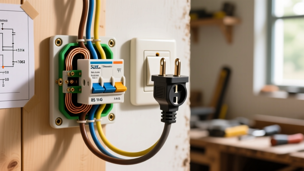
When homeowners and DIYers refer to an electrical switch outlet, they are typically describing one of two distinct wiring configurations. The first is a switched receptacle (often called a half-hot outlet), where a standard duplex receptacle is wired so that one half is controlled by a wall switch while the other remains constantly hot. The second is a switch/receptacle combo device (such as the Leviton 5241 or Cooper Wiring Devices 4731), which combines a single toggle switch and a single duplex receptacle into one standard 1-gang wall plate. Troubleshooting a dead electrical switch outlet requires you to first identify which of these two setups you are dealing with, as the failure modes and diagnostic steps differ significantly.
In 2026, with the widespread adoption of AFCI/GFCI dual-function breakers and strict Tamper-Resistant (TR) mandates under the latest NEC cycles, a dead outlet is rarely just a "bad receptacle." It is often a symptom of an upstream trip, a failed push-in backstab connection, or a misconfigured switch loop. Below, we break down the exact diagnostic flow used by licensed electricians to isolate and repair these circuits.
Diagnostic Matrix: Symptoms and Probable Causes
Before pulling out the screwdriver, match your specific symptom to this diagnostic matrix to narrow down the failure point.
| Symptom | Probable Cause | Diagnostic Action |
|---|---|---|
| Both halves of a switched receptacle are dead. | Tripped upstream GFCI/AFCI or tripped breaker. | Check panel and upstream wet-location receptacles. |
| Bottom half is dead; top half is always hot. | Wall switch failure or broken switch loop wire. | Test switch terminals for 120V continuity when toggled. |
| Both halves are constantly hot; switch does nothing. | Brass break-off tab was not removed during install. | Remove receptacle and inspect the brass fin between screws. |
| Combo device outlet works, but the toggle switch is dead. | Internal switch mechanism failure or loose line-side hot. | Bypass combo device; test incoming hot with a multimeter. |
| Outlet works only when a specific light is turned on. | Neutral wire incorrectly wired in series (switch loop error). | Verify white wire is not carrying 120V; check neutral bus. |
Step-by-Step Multimeter Troubleshooting
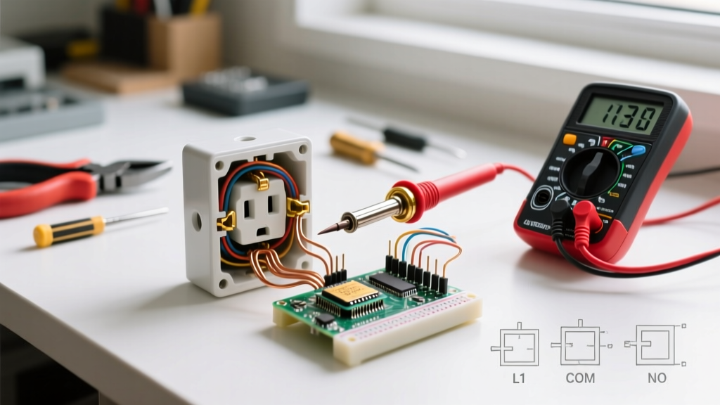
To accurately diagnose an electrical switch outlet, you must move beyond cheap neon voltage testers. You need a True-RMS digital multimeter (DMM) with a low-impedance (LoZ) mode, such as the Fluke 117, to eliminate ghost voltage readings caused by capacitive coupling in modern Romex cables.
Step 1: Verify Incoming Power and Eliminate Ghost Voltage
Turn off the breaker, remove the wall plate, and pull the device from the gang box. Turn the breaker back on. Set your Fluke 117 to LoZ V AC. Insert the black probe into the neutral (silver) terminal slot and the red probe into the hot (brass) terminal slot.
- Reading 118V - 122V: You have a solid, healthy incoming hot. The issue is downstream or within the device itself.
- Reading 0V: The circuit is dead upstream. Check for a tripped GFCI in an adjacent bathroom, kitchen, or garage. According to the Consumer Product Safety Commission (CPSC), hidden GFCI trips are the leading cause of perceived "dead outlet" complaints in residential wiring.
- Reading 40V - 80V (Ghost Voltage): Switch to LoZ mode. If the voltage drops to near 0V, you have an open neutral or a broken hot wire somewhere in the daisy chain.
Step 2: Testing the Switch Loop (For Half-Hot Receptacles)
If the top half of your receptacle has 120V but the bottom half is dead, the wall switch controlling the bottom half is likely the culprit. In a standard switch loop, power goes to the receptacle first, then a 14/2 or 12/2 cable runs up to the switch.
- Locate the two wires connected to the switch (usually one black, one white). Note: Per NEC code, the white wire in this scenario must be re-identified with black electrical tape or marker to indicate it is being used as a hot return, not a neutral.
- With the switch in the "ON" position, measure across the two switch screws. You should read 0.1V to 0.5V (voltage drop across a closed circuit).
- If you read 120V across the switch screws while it is in the "ON" position, the internal contacts of the toggle switch have failed. Replace the switch with a standard 15A single-pole toggle (e.g., Leviton 1451).
The Infamous Break-Off Tab: The #1 DIY Mistake
When converting a standard duplex receptacle into a switched electrical switch outlet, the installer must snap off the brass connecting tab (fin) on the hot side. This tab connects the top and bottom brass screws. If it is left intact, the wall switch will attempt to backfeed the entire receptacle, or the constant hot will bypass the switch entirely, rendering the switch useless.
Expert Tip: Never break the silver (neutral) tab unless you are dealing with a multi-wire branch circuit (MWBC) sharing a neutral from two different breaker phases. Breaking the neutral tab on a standard single-pole circuit will result in an open neutral, which can cause severe voltage fluctuations and damage connected electronics.
If you are troubleshooting a newly installed outlet where the switch does nothing, use a pair of needle-nose pliers to grip the brass tab between the two hot screws and bend it back and forth until it snaps clean off. Ensure no small brass shards are left bridging the gap.
Troubleshooting Switch/Receptacle Combo Devices
Combo devices like the Leviton 5241 (15A) or Leviton 5641 (15A, wider spacing) are incredibly common in basements, laundry rooms, and older kitchens where a light and an appliance plug are needed in a single 1-gang box. These devices have internal isolation, meaning there is no external tab to break.
Wiring Configurations for Combo Devices
Combo devices can be wired in two distinct ways. Identifying which method was used is critical for troubleshooting:
- Configuration A (Switch controls an external light; Outlet is always hot): The incoming hot is pigtailed to both the brass "Line" screw on the receptacle and the brass screw on the switch. The switch's second screw sends power out to a light fixture. If the outlet is dead but the light works, the internal bus connecting the receptacle to the line terminal has failed. Replace the unit.
- Configuration B (Switch controls the outlet itself): A small metal jumper (often included in the box) or a short pigtail wire connects the switch's "Load" terminal directly to the receptacle's brass "Line" terminal. If the outlet is dead, check this jumper wire. It frequently vibrates loose in high-traffic areas like laundry rooms where heavy appliances cause wall vibration.
Push-In Backstab Failures vs. Screw Terminals
If your electrical switch outlet intermittently loses power when you plug in a high-draw device (like a vacuum or space heater), the issue is almost certainly a failed "backstab" push-in connection. While UL 498 standards permit push-in terminals for 14 AWG wire on 15A devices, the internal spring-steel grips degrade over time due to thermal expansion and contraction.
According to data referenced in the NFPA 70 National Electrical Code safety guidelines, loose connections are a primary precursor to electrical arcing and residential fires. When troubleshooting, always pull the wires out of the backstab holes. Use a wire stripper to create a fresh, clean J-hook on the solid copper wire, and secure it under the side screw terminals. Torque the screw until the lock washer is fully compressed and the wire cannot be pulled free with a firm tug. For 12 AWG wire on 20A circuits, backstabbing is strictly prohibited by code; screw terminals or approved push-lock lever connectors (like Wago 221 series) must be used.
Advanced Edge Case: The Shared Neutral (MWBC)
In some older homes, an electrical switch outlet might be wired on a Multi-Wire Branch Circuit (MWBC). This setup uses a 14/3 or 12/3 cable where the red wire feeds the switch, the black wire feeds the constant hot, and they share a single white neutral. If a previous homeowner replaced the panel or swapped breakers and accidentally moved the black and red wires onto the same phase leg (instead of opposite 120V legs), the shared neutral will carry the sum of the currents rather than the difference. This leads to melted neutral insulation and a dead outlet. To test for this, use a clamp meter around the white neutral wire while running loads on both the top and bottom receptacles. If the neutral current exceeds 15A, you have a phasing error at the breaker panel that requires immediate correction by a licensed professional.
Summary Checklist for a Successful Repair
- Verify breaker and upstream GFCI status using a non-contact voltage tester (e.g., Klein Tools NCVT-3).
- Test incoming voltage with a True-RMS multimeter in LoZ mode to rule out ghost voltage.
- Inspect the brass break-off tab on standard duplex receptacles used in half-hot configurations.
- Check for white wires re-identified as hot in switch loops.
- Migrate all backstabbed 14 AWG and 12 AWG wires to screw terminals or lever nuts.
- Ensure all combo device jumper wires are tightly secured under the terminal screws.
By following this structured diagnostic approach, you can reliably identify whether your electrical switch outlet failure is a simple mechanical break, a wiring topology error, or an upstream protection trip, saving hours of frustrating trial and error.
Frequently Asked Questions
Can I use a smart switch to control a half-hot electrical switch outlet?
Yes, but you must ensure the smart switch (like the Lutron Maestro or Kasa Smart) has a neutral wire requirement that your gang box can fulfill. Standard switch loops often lack a neutral, which will prevent most modern Wi-Fi-enabled smart switches from powering on.
Why does my switched outlet hum when the switch is off?
A faint hum usually indicates capacitive coupling or a failing dimmer switch. If a standard toggle switch is humming, the internal contacts are arcing due to a loose wire or a failing spring mechanism. Replace the switch immediately to prevent a fire hazard.