
Why Reading the Electrical Wall Outlet Symbol Matters Before You Wire
Before you strip your first 12 AWG NM-B cable or snap a nail-on bracket to a stud, you need to know exactly where your receptacles are going. For beginners stepping into their first DIY rough-in or renovation, the blueprint is your ultimate roadmap. However, architectural plans do not draw realistic pictures of duplex receptacles; instead, they rely on standardized schematic shorthand. Understanding the electrical wall outlet symbol is the critical 'Step Zero' of any successful installation project. Misinterpreting these symbols can lead to failed inspections, drywall patching nightmares, and costly rewiring. This guide bridges the gap between 2D architectural symbols and 3D physical installation, giving you the exact knowledge needed to translate a printed plan into a code-compliant reality in 2026.
The Anatomy of Standard Outlet Symbols
In the United States, architectural and electrical drawings generally follow the guidelines set by the US National CAD Standard (NCS) and ANSI Y32.9. When you look at a floor plan, the standard electrical wall outlet symbol for a basic 15-amp or 20-amp 120V duplex receptacle is represented by a semi-circle with two parallel lines extending outward from the flat edge. The flat edge is typically placed against the wall line on the drawing to indicate surface mounting.
However, modern homes require more than just standard duplex outlets. As of the 2026 construction season, with the widespread adoption of the 2023 National Electrical Code (NEC), you will frequently encounter modified symbols indicating specialized receptacles. These modifiers are usually denoted by text abbreviations next to the symbol or specific hash marks.
Decoding Common Receptacle Variations
| Symbol Description | Meaning | Typical Installation Location |
|---|---|---|
| Semi-circle + 2 parallel lines | Standard 120V Duplex Receptacle (15A or 20A) | Living rooms, bedrooms, hallways |
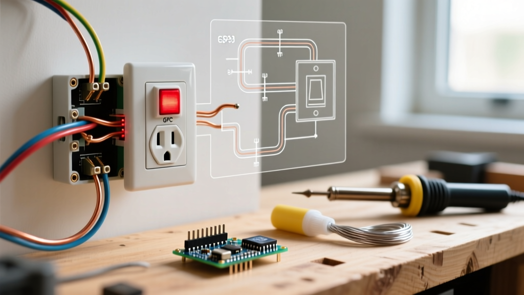
| Semi-circle + 2 lines + 'GFCI' or 'GF' | Ground Fault Circuit Interrupter | Bathrooms, kitchens, garages, outdoors |
| Semi-circle + 2 lines + 'AFCI' | Arc Fault Circuit Interrupter (Often via breaker) | Bedrooms, living areas (NEC 210.12) |
| Semi-circle + 2 lines + 'WP' | Weatherproof / In-Use Cover Required | Exterior walls, patios, pool equipment |
| Semi-circle + 2 lines + '$' or 'SW' | Switched Receptacle (Half-hot or fully switched) | Living rooms (for lamps), dining rooms |
| Circle with crosshairs or square box | Floor Receptacle / Floor Box | Large open-concept living areas, home offices |
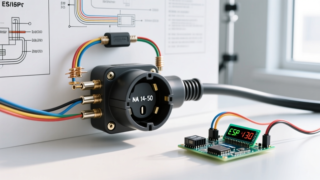
| Semi-circle + '250V' or '50A' | High-Voltage Receptacle (e.g., NEMA 14-50R) | EV charging stations, electric ranges, dryers |
Translating the Symbol to Physical Rough-In Steps
Once you have identified the electrical wall outlet symbol on your blueprint, you must translate that 2D mark into a physical location on your wall studs. Here is the professional workflow for transferring blueprint data to the job site.
Step 1: Verify the Blueprint Scale
Most residential electrical plans are drawn at a 1/4-inch = 1-foot scale (1/4' = 1'-0'). Use an architectural scale ruler to measure the exact distance from the nearest corner stud or door casing to the center of the outlet symbol. If the plan shows the outlet 4 feet from the corner of the room, measure exactly 48 inches along your physical bottom plate and mark the stud.
Step 2: Determine the Mounting Height (AFF)
Blueprints rarely specify the vertical height of standard wall outlets unless they are for ADA compliance or specific appliance clearances. The industry standard for residential rough-in is 16 inches AFF (Above Finished Floor) to the center of the electrical box. This accounts for standard baseboards and provides easy access. If you are installing in a space requiring ADA compliance, the minimum height is 15 inches AFF to the center of the receptacle, as outlined by the U.S. Department of Justice ADA Design Standards.
Step 3: Select and Install the Correct Box
Do not just grab any blue plastic box. Match the box to the symbol and the wall cavity:
- Standard Interior Drywall: Use a Carlon B114R (single-gang, 14 cubic inch) or B120R (single-gang, 20 cubic inch) nail-on bracket. The 20-cubic-inch box is highly recommended for 12 AWG wire to prevent overcrowding.
- Fire-Rated Walls (Garage to Living Space): You must use a metal box or install fire-putty pads (like 3M Fire Barrier Putty) over plastic boxes to maintain the fire rating.
- Masonry or Concrete: Use cast-in-place concrete boxes or masonry rings if drilling into block walls.
Code Compliance: NEC Spacing Rules for Outlet Symbols
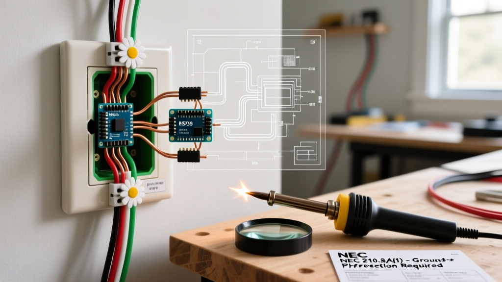
When reviewing a blueprint, you might notice that the architect has placed electrical wall outlet symbols at seemingly arbitrary intervals. This is not random; it is dictated by NEC Article 210.52(A)(1). According to the National Fire Protection Association (NFPA), which publishes the NEC, the '6-foot rule' applies to most habitable rooms.
The 6-Foot / 12-Foot Rule:
No point measured along the floor line in any wall space can be more than 6 feet from a receptacle outlet. Furthermore, any wall space that is 2 feet or more in width (including space interrupted by doorways, fireplaces, and similar openings) must have its own dedicated outlet symbol and physical receptacle.
As a beginner, if you are designing your own layout or modifying an existing blueprint, use a laser measure to ensure no point along your baseboards exceeds this 6-foot limit. Failing to do so will result in an immediate failed rough-in inspection.
Pro Tips: Avoiding Common Blueprint Misinterpretations
Even with a clear understanding of the electrical wall outlet symbol, beginners often make critical errors during the physical installation. Keep these expert tips in mind:
- Beware of 'Switched' Symbols: If the symbol has a '$' or is tied via a dotted line to a wall switch symbol, you must run a 3-wire cable (12/3 or 14/3 NM-B) to that box, or wire it with a switch loop, to allow half of the duplex receptacle to be controlled by the wall switch. Wiring it as a standard always-hot outlet will fail the final trim-out test.
- Account for Cabinetry and Tile: In kitchens and bathrooms, the electrical wall outlet symbol on the plan might be placed 44 inches AFF. However, if you are installing thick quartz countertops and a stone backsplash, measure from the *finished* counter height, not the rough plywood sub-top, to ensure the box doesn't end up buried behind the backsplash.
- Heavy Load Blocking: If the blueprint shows a 240V NEMA 14-50R symbol for an EV charger in the garage, do not just nail the box to a single stud. The physical weight of the heavy-gauge 6/3 NM-B cable and the robust receptacle requires plywood blocking between the studs to support the dynamic load of plugging and unplugging a stiff EV cable.
Frequently Asked Questions (FAQ)
What does a circle with a 'C' inside mean next to an outlet symbol?
A circle with a 'C' typically denotes a ceiling-mounted outlet or a specific junction box location, but if placed adjacent to a wall outlet symbol, it often indicates a required blank cover plate or a specific communication/coaxial drop integrated into the same gang box.
Can I add an outlet where there is no symbol on the blueprint?
Yes, blueprints represent the *minimum* code requirements. Adding extra outlets for convenience (like behind a planned TV mount or a home office desk) is highly recommended and perfectly legal, provided you do not exceed the circuit's amperage capacity and follow NEC box-fill calculations.
Why are some outlet symbols drawn with a triangle?
A triangle superimposed over or next to the standard semi-circle outlet symbol usually designates an isolated ground (IG) receptacle. These are typically orange in color and are used in environments with sensitive electronic equipment (like home studios or medical rooms) to reduce electromagnetic interference.