
Introduction: Bridging Wiring Diagrams and Physical Reality
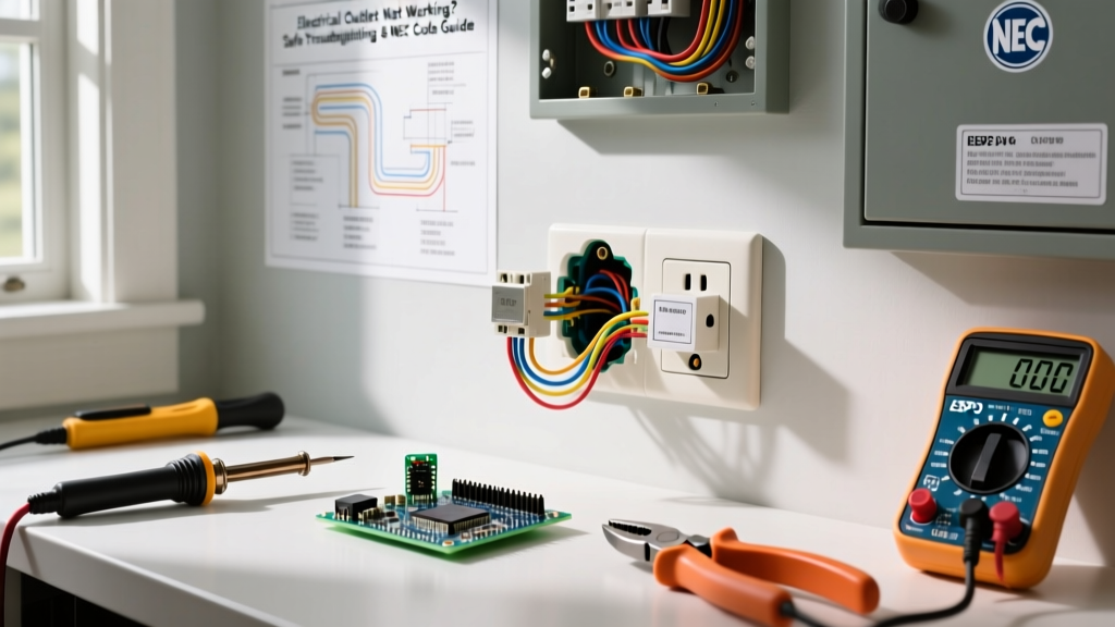
When designing or interpreting a wiring diagram, it is easy to get lost in the theoretical flow of electrons, forgetting the physical constraints of the installation. A wiring diagram is merely a map; the electrical outlet box types you select represent the actual terrain. If the physical box cannot accommodate the conductors, devices, and clamps dictated by your diagram, the installation will fail inspection, overheat, or cause a fire. This reference guide bridges the gap between 2D electrical schematics and 3D physical enclosures, providing the exact specifications, National Electrical Code (NEC) calculations, and product models required for modern 2026 installations.
The Wiring Diagram Connection
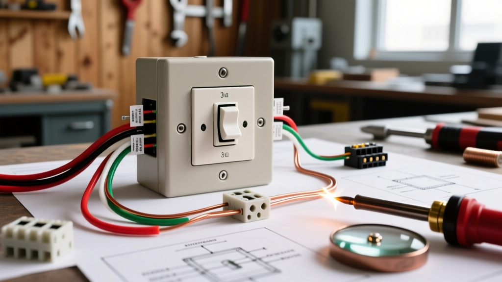
Every line on a wiring diagram translates to physical volume inside a box. A standard single-pole switch diagram might show two wires and a ground. However, a 4-way switch loop with 12/3 NM-B cable introduces multiple current-carrying conductors, pigtails, and wire nuts. Understanding electrical outlet box types ensures you select an enclosure with the correct cubic-inch (cu. in.) capacity and depth to safely house the physical manifestation of your schematic.
Primary Electrical Outlet Box Types
Boxes are categorized by shape, mounting method, and intended application. Selecting the correct type is the first step in translating a wiring diagram into a safe physical installation.
- Single-Gang Rectangular (Nail-On / New Work): The standard for residential framing. These feature integral nail brackets for mounting to wooden studs before drywall is laid. Reference Model: Carlon B618R-UPC (18 cu. in., PVC). Ideal for standard single receptacles or single-pole switches.
- Single-Gang Old Work (Remodel): Designed for retrofitting into finished walls. They utilize flip-out clamps or 'Madison' hangers that grip the back of the drywall. Reference Model: Raco 101 (14 cu. in., Galvanized Steel). Best for adding a single outlet to an existing room without tearing down drywall.
- Double-Gang and Multi-Gang Boxes: Required when a wiring diagram calls for dual receptacles, a combination switch/receptacle, or side-by-side smart dimmers. They provide the necessary horizontal width but require careful stud placement or specialized hanger bars.
- 4-Square (Square) Boxes: Heavy-duty enclosures used in commercial, industrial, or exposed-conduit residential applications. They offer massive volume and accommodate multiple conduit knockouts. Reference Model: Raco 5315-0 (21 cu. in., 1.5-inch deep steel). Often paired with a 'mud ring' or 'plaster ring' to adapt to single or double-gang faceplates.
- Octagonal and Round Boxes: Primarily reserved for ceiling-mounted wiring diagrams, such as light fixtures, ceiling fans, or junction splices. They are not used for standard wall outlets. Fan-rated octagonal boxes feature reinforced mounting brackets to handle dynamic loads up to 70 lbs.
Material Matrix: Metallic vs. Non-Metallic
The choice of material impacts grounding requirements, fire ratings, and compatibility with conduit systems. The NEC outlines strict rules for grounding metallic enclosures to ensure fault currents have a low-impedance path back to the source.
| Material | Common Use Case | Grounding Requirement | Pros & Cons |
|---|---|---|---|
| PVC (Non-Metallic) | Residential wood framing, NM-B (Romex) cable | Box itself is not grounded; equipment grounding conductor (EGC) must be spliced and bonded to the device. | Pros: Rust-proof, cheap, easy to machine. Cons: Cannot be used with metal conduit, brittle in extreme cold. |
| Galvanized Steel | Commercial, exposed basement walls, metal conduit (EMT/IMC) | Box must be bonded to the EGC or grounded via the metallic conduit path per NEC 250.148. | Pros: High crush resistance, fire-rated, acts as a ground path. Cons: Heavier, requires locknuts/bushings, can rust if coating is damaged. |
| Die-Cast Aluminum | Wet locations, exterior outlets, weatherproof installations | Must be bonded; requires specific anti-oxidant paste when mating with dissimilar metals. | Pros: Excellent corrosion resistance, durable. Cons: Expensive, requires careful threading. |
NEC Box Fill Calculations (Article 314.16)
The most critical intersection between a wiring diagram and an electrical box is the Box Fill Calculation. The NEC strictly limits how many conductors can enter a box based on its cubic-inch volume and the gauge of the wire. Overcrowding a box damages wire insulation during the stuffing process, leading to short circuits and arc faults.
NEC Article 314.16(B) Summary: Each conductor originating outside the box and terminating or splicing inside counts as one volume allowance. Conductors that simply pass through the box without a splice count as one allowance. A single equipment grounding conductor (or multiple EGCs) counts as one volume allowance total, based on the largest EGC present. Internal clamps and device yokes (switches/receptacles) also require volume allowances.
Wire Gauge Volume Allowance Chart
Use this chart to calculate the cubic inches required per conductor when translating your wiring diagram into physical box fill math.
| Wire Size (AWG) | Volume Allowance per Conductor | Common Application |
|---|---|---|
| 14 AWG | 2.0 cu. in. | 15-Amp lighting and receptacle circuits |
| 12 AWG | 2.25 cu. in. | 20-Amp kitchen, bathroom, and general receptacles |
| 10 AWG | 2.5 cu. in. | 30-Amp water heaters, dryers, HVAC |
| 8 AWG | 3.0 cu. in. | 40-Amp to 50-Amp heavy appliances |
| 6 AWG | 5.0 cu. in. | 60-Amp subpanels, EV chargers |
Real-World Scenarios: Matching Boxes to Complex Diagrams
Let us apply these calculations to common 2026 wiring diagrams to demonstrate why box selection is paramount.
Scenario A: The Smart Dimmer Switch Installation
Modern smart switches, such as the Lutron Caseta (PD-6WCL) or Kasa Matter-compatible dimmers, feature bulky internal relays and Wi-Fi/Zigbee antennas. A standard single-gang PVC box (18 cu. in., 2.5-inch depth) is often physically too shallow to accommodate the 1.75-inch depth of the smart switch body plus the pushed-back wire nuts.
Expert Solution: When your wiring diagram includes a smart switch, specify a deep single-gang box like the Carlon A226R-UPC (26 cu. in., 3.5-inch depth). This prevents the crushing of the neutral pigtail wire nut against the back of the box, a common failure point that causes intermittent flickering or total device failure.
Scenario B: Multi-Way (3-Way / 4-Way) Switch Loops
Consider a 3-way switch wiring diagram at the 'line' box. You have a 12/2 NM-B feeding power in, and a 12/3 NM-B feeding the travelers to the next switch. Let us calculate the box fill for 12 AWG wire (2.25 cu. in. per allowance):
- 12/2 In: 2 current-carrying conductors (Hot, Neutral) = 2 allowances (4.5 cu. in.)
- 12/3 Out: 3 current-carrying conductors (Common, 2 Travelers) = 3 allowances (6.75 cu. in.)
- Grounds: 1 allowance for all EGCs = 2.25 cu. in.
- Switch Device: 2 allowances = 4.5 cu. in.
- Total Minimum Volume: 18.0 cu. in.
While an 18 cu. in. box technically passes the math, physically bending five 12 AWG THHN/NM-B wires into an 18 cu. in. box is incredibly difficult and risks insulation damage. Best Practice: Always upsize to a 22 cu. in. or 26 cu. in. deep box for 3-way and 4-way junction points to ensure a safe, clean installation.
Expert Troubleshooting & Edge Cases
When field conditions clash with the original wiring diagram, use these expert troubleshooting protocols:
- The 'Overstuffed' Box Heat Issue: If an existing outlet feels warm to the touch, check the box fill. Overcrowded boxes trap ambient heat generated by the receptacle's internal contacts, especially on 20-Amp circuits running near capacity. Upgrade to a deeper box or split the circuit.
- Metal Box Grounding Verification: When replacing a plastic box with a steel box in an older home, ensure the metal box is bonded. If the wiring diagram lacks an EGC (common in pre-1960s Knob & Tube or early BX cable), you must either run a new ground wire back to the panel or install a GFCI receptacle labeled 'No Equipment Ground' per NEC 406.4(D)(2).
- Conduit Body Limitations: Do not confuse conduit bodies (Type LB, LL, LR) with standard junction boxes. Conduit bodies are generally not permitted to contain splices unless they are specifically listed for it and marked with a cubic-inch volume rating. If your diagram requires a splice in a conduit run, use a proper junction box.
Authoritative References
For further reading on electrical safety standards, box fill mandates, and installation codes, consult the following authoritative resources:
- National Fire Protection Association (NFPA) - National Electrical Code Resources: The definitive source for NEC Article 314 and all electrical installation standards.
- Occupational Safety and Health Administration (OSHA) - Electrical Safety Guidelines: Critical safety protocols for working with electrical enclosures and live circuits.