
The Definitive Guide to Electrical Socket Wiring
Electrical socket wiring is the backbone of residential power distribution. Whether you are upgrading a vintage home or installing a dedicated 240V circuit for an EV charger, understanding the physics, code requirements, and mechanical nuances of receptacles is non-negotiable. The National Electrical Code (NEC NFPA 70) mandates strict adherence to grounding, torque, and fault-protection standards to prevent arc faults and thermal fires.
In this guide, we dissect five of the most common electrical socket wiring scenarios encountered by professionals and advanced DIYers. We will cover exact torque specifications, wire stripping measurements, and the critical differences between line and load configurations.
Scenario 1: Standard 15A/20A Duplex Receptacles (Middle vs. End-of-Run)
The standard 120V duplex receptacle (like the Leviton T5262-HGY for 15A or T5362-HGY for 20A) is the most ubiquitous device in residential wiring. Priced between $3 and $6, these Tamper-Resistant (TR) devices feature internal shutters that require simultaneous pressure to insert a plug, satisfying NEC 406.12.
Side-Wiring vs. Push-In Back-Wiring
Never use the push-in 'back-wire' holes for 12 AWG wire or high-load circuits. The internal spring-loaded clamps degrade under thermal expansion, leading to high-resistance connections and melted faceplates. Always use the side terminal screws or the screw-clamp 'back-wiring' plates found on commercial-grade (spec-grade) receptacles.
- Wire Stripping: Strip exactly 5/8 inch of insulation for 14 AWG and 12 AWG solid copper wire.
- Terminal Torque: Tighten brass and silver screws to 14 in-lbs. Use a calibrated torque screwdriver like the Klein Tools 69112 to prevent strip-out or under-tightening.
Comparing Run Configurations
| Feature | End-of-Run Wiring | Middle-of-Run Wiring |
|---|---|---|
| Cable Count | One 2-wire or 3-wire NM cable | Two 2-wire or 3-wire NM cables |
| Hot/Neutral Routing | Direct to single brass/silver screw | Pigtailed or daisy-chained via screws |
| Grounding Rule | Ground to green screw only | Pigtail grounds together + to green screw |
| Box Fill Impact | Lower cubic inch requirement | Higher cubic inch requirement |
Expert Tip: When wiring the middle of a run, do not daisy-chain the neutral wires through the receptacle's silver screws if the circuit is a Multi-Wire Branch Circuit (MWBC). A broken neutral downstream can push 240V across 120V appliances. Always pigtail MWBC neutrals.
Scenario 2: GFCI Receptacles (Line vs. Load Configurations)
Ground Fault Circuit Interrupter (GFCI) receptacles, such as the Leviton GFNT2-W (Slim model, $18-$24), are mandated by NEC 210.8 for kitchens, bathrooms, garages, outdoors, and unfinished basements. They detect current imbalances as small as 4 to 6 milliamps and trip in under 25 milliseconds.
Wiring the LINE and LOAD Terminals
The most frequent failure mode in DIY GFCI installation is reversing the Line and Load wires.
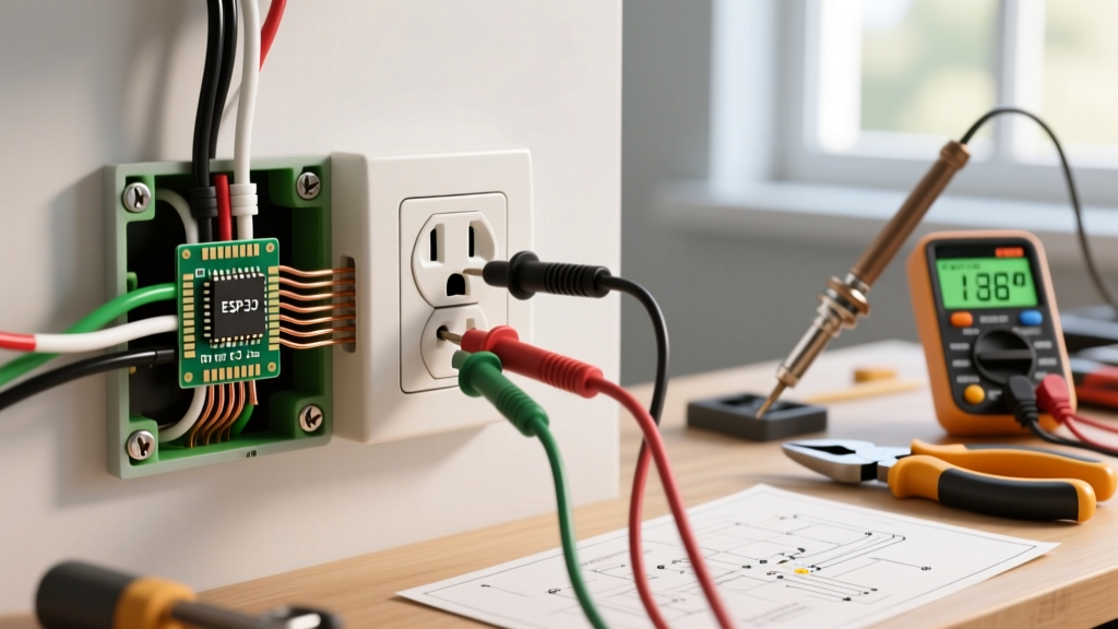
- Identify the Line: Use a non-contact voltage tester (NCVT) and a multimeter to identify the incoming hot and neutral wires from the breaker panel. These connect to the terminals marked LINE.
- Identify the Load: The wires continuing to downstream outlets connect to the LOAD terminals. This extends GFCI protection to subsequent sockets.
- Grounding: Connect the bare copper ground to the green screw. If using a metal junction box, you must also run a 14 AWG or 12 AWG copper pigtail from the ground screw to the metal box using a green grounding clip or 10-32 grounding screw.
Safety Warning: If you only need to protect the single receptacle and no downstream devices, cap the LOAD wires with wire nuts and only wire the LINE terminals. Cover the unused LOAD terminals with the included 'No Equipment Ground' or warning stickers if applicable.
Scenario 3: Split-Wired (Switched) Receptacles
Split-wired receptacles are heavily utilized in living rooms (where one half is controlled by a wall switch for lamps, and the other is always hot) and kitchens (powering a garbage disposal and dishwasher on separate circuits).
The Break-Off Tab Technique
To create a split-wired socket, you must remove the connecting brass tab on the hot side of the receptacle using needle-nose pliers. Do not break the silver (neutral) tab unless you are wiring a specialized MWBC setup with two independent hot legs and a shared neutral.
- Top Receptacle (Switched): Wire the switched hot (usually a black or red wire returning from the wall switch) to the top brass screw.
- Bottom Receptacle (Always Hot): Wire the continuous hot from the panel to the bottom brass screw.
- Neutral and Ground: Wire the white neutral to the silver screw and the bare ground to the green screw. These remain shared across both halves.
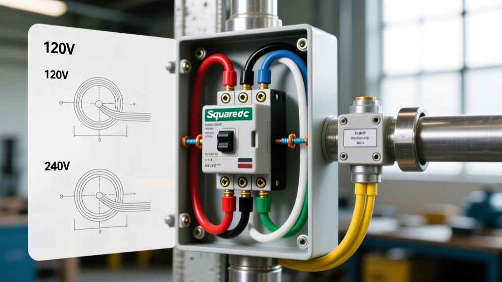
Code Requirement: If the two hot wires originate from a 240V double-pole breaker (an MWBC), NEC 210.4(B) requires a simultaneous disconnect mechanism, meaning you must use a handle-tie on the breaker or a dedicated 2-pole breaker to ensure both halves lose power during maintenance.
Scenario 4: High-Voltage NEMA 14-50 (EV Chargers and Dryers)
The NEMA 14-50R is a 50-Amp, 125/250V receptacle featuring two hots, a neutral, and a dedicated ground. With the surge in residential EV adoption, the Department of Energy notes that proper 14-50 installation is critical for Level 2 charging safety. High-quality models like the Hubbell 9450A ($35-$45) feature heavy-duty thermoset faces and robust terminal clamps.
Heavy-Gauge Wiring Specifications
Wiring a 14-50 requires 6 AWG copper or 4 AWG aluminum conductors. Because of the continuous load nature of EV charging (often drawing 40A for hours), thermal expansion at the terminals is a major risk.
- Stripping Length: Strip exactly 3/4 inch of insulation from the 6 AWG wires. Exposing too much bare wire creates a shock hazard; too little causes the screw to bite into the insulation, resulting in an arc fault.
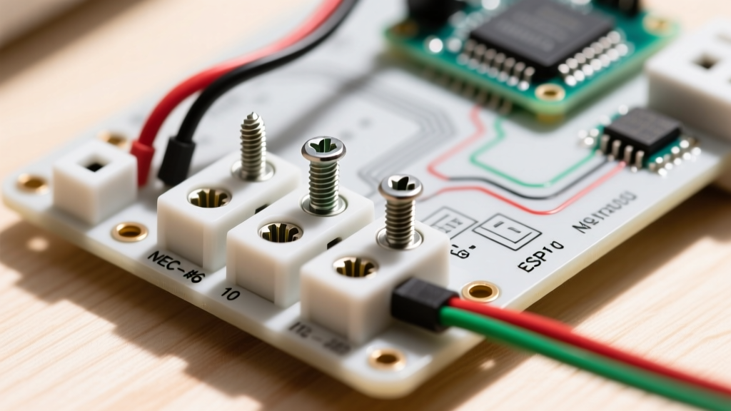
- Torque Specs: Heavy-duty terminals require significantly more torque than standard 15A outlets. Consult the manufacturer's spec sheet, but typical 14-50 terminal screws require between 45 and 50 in-lbs of torque. Use an inch-pound torque wrench.
- Neutral vs. Ground: The 4-prong NEMA 14 configuration strictly separates the neutral (white wire, center terminal) and ground (bare/green wire, bottom U-shaped terminal). Never bond the neutral to the ground at the receptacle; bonding is only permitted at the main service panel.
Scenario 5: Dual Function AFCI/GFCI Receptacles
Modern NEC updates require both Arc Fault (AFCI) and Ground Fault (GFCI) protection in specific areas like laundry rooms and kitchens. While AFCI breakers in the panel are common, dual-function AFCI/GFCI receptacles (like the Leviton AGFTR2-W, $35-$45) offer localized protection and easier troubleshooting.
Wiring these is identical to a standard GFCI (Line/Load), but the physical footprint is deeper. You must ensure your junction boxes have adequate cubic inch volume. A standard single-gang plastic box (18 cubic inches) is often too cramped for the thick 12 AWG wires and the deep body of a dual-function device. Upgrade to a 22.5 cubic inch 'deep' box to prevent wire crimping and insulation damage during device push-in.
Troubleshooting Common Wiring Failures
Even with meticulous installation, faults can occur. The Consumer Product Safety Commission (CPSC) emphasizes regular testing of electrical safety devices. Use a professional-grade tester like the Klein Tools RT212 to diagnose these common scenarios:
- Open Neutral: The tester shows no voltage, but a multimeter reads 120V from Hot to Ground. This indicates a disconnected or broken white wire downstream or at the panel. Check for back-wired push-in failures.
- Hot/Neutral Reversed: The receptacle functions, but the wide blade (neutral) is energized. This is a severe shock hazard, especially for appliances with metal chassis. Swap the brass and silver wire connections.
- Bootleg Ground: A tester shows 'Correct', but a ground-to-neutral voltage check reads 0.0V, and a ground-to-hot check reads 120V. This means the ground screw is illegally jumpered to the neutral silver screw inside the box. Remove the jumper immediately and run a proper equipment grounding conductor.
- Phantom Voltage: Digital multimeters may read 40V-90V on a disconnected wire due to capacitive coupling from adjacent live wires in the same NM cable. Use a solenoid voltage tester (Wiggy) or a low-impedance (LoZ) multimeter setting to verify true dead circuits before touching wires.
Final Thoughts on Safety and Compliance
Electrical socket wiring is not merely about making a device function; it is about ensuring long-term thermal stability and life-safety protection. Always de-energize the circuit at the main breaker, verify with a CAT III or CAT IV rated multimeter, and adhere strictly to local code adoptions of the NEC. When in doubt, or when dealing with main panel modifications and MWBC installations, consult a licensed master electrician.