
The Unique Landscape of the UK Electrical Outlet
The electrical outlet UK standard, formally known as BS 1363, is globally unique. Unlike North American NEMA 5-15R or European Schuko sockets, the UK 13-amp fused plug and socket system incorporates integrated safety shutters, individual plug fusing, and a robust earth pin designed to open the live and neutral shutters. While this design is inherently safe, improper installation, degraded terminals, or faulty ring final circuit topologies can introduce severe fire and shock hazards.
Whether you are a DIY enthusiast verifying a newly installed socket or an electrician preparing for a periodic inspection, testing an electrical outlet UK style requires strict adherence to the BS 7671:2018+A2:2022 (18th Edition) Wiring Regulations. This comprehensive guide details the exact procedures, tooling, and failure modes associated with UK socket inspection.
Essential Tooling for UK Socket Verification
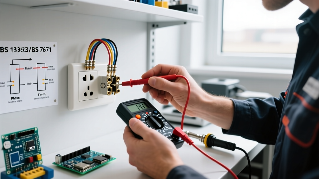
Accurate testing goes far beyond a simple neon screwdriver. To properly inspect and certify an electrical outlet UK installation, you need calibrated equipment compliant with HSE GS38 guidelines for test leads.
- Simple Socket Checker (e.g., Martindale EZ150+): Priced around £45, this plug-in tester checks for basic wiring faults like reverse polarity, open earth, or open neutral. It does not measure earth loop impedance or verify RCD trip times.
- Digital Multimeter (e.g., Fluke T6-1000): Essential for safe isolation, voltage verification, and continuity testing. Expect to pay between £180 and £220 for a CAT III/IV rated model.
- Multifunction Installation Tester / MFT (e.g., Megger MFT1835 or Fluke 1663 FC): Mandatory for issuing legal certification (EIC or MEIWC). These £1,200–£1,600 devices measure Earth Fault Loop Impedance (Zs), prospective fault current (PFC), and precise RCD trip times in milliseconds.
- VDE Torque Screwdriver: Modern UK sockets (like the MK Logic Plus or Schneider Lisse ranges) specify terminal torque settings, typically between 1.2 Nm and 2.0 Nm. A calibrated Wera VDE torque screwdriver (£110) prevents strand shearing and thermal loosening.
Phase 1: Safe Isolation and Visual Inspection
Before removing the faceplate of any electrical outlet UK standard, you must perform a verified safe isolation procedure. The Health and Safety Executive (HSE) mandates that you identify the correct circuit, switch off the MCB, lock off the consumer unit, and prove your voltage indicator on a known source, the dead circuit, and the known source again.
Dead Testing: Visual & Mechanical Checks
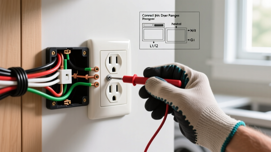
Once isolated and the faceplate is removed, inspect the backbox and terminations:
- Backbox Depth: For a 2.5mm² ring final circuit, a minimum 35mm deep metal backbox (or 47mm for plasterboard dry-lining boxes) is required. Shallow boxes cause cable crowding, leading to insulation damage and poor heat dissipation.
- Earth Sleeving: The bare Circuit Protective Conductor (CPC) must be sleeved with green/yellow PVC. Exposed bare copper inside the backbox is a direct violation of BS 7671.
- Conductor Routing: Ensure the brown (live) and blue (neutral) conductors are not trapped behind the earth wire or pinched against the faceplate screw lugs.
- Terminal Integrity: Check for signs of thermal stress (brown/black scorch marks). If the insulation is brittle or melted, the terminal was likely under-torqued, causing high resistance and arcing.
Phase 2: Ring Final vs. Radial Circuit Verification
The UK heavily utilizes the Ring Final Circuit (RFC), a topology rarely seen outside the British Isles. A standard RFC uses 2.5mm² twin and earth cable protected by a 32A Type B MCB. Radial circuits typically use 2.5mm² (20A MCB) or 4.0mm² (32A MCB).
The Figure-of-8 Continuity Test
To verify an electrical outlet UK ring circuit is correctly wired and not a 'borrowed neutral' or broken ring, perform end-to-end continuity testing at the consumer unit before energizing:
- r1 (Live): Measure end-to-end resistance of the brown conductors.
- rn (Neutral): Measure end-to-end resistance of the blue conductors.
- r2 (Earth): Measure end-to-end resistance of the CPC.
Expert Insight: Because the CPC in standard 2.5mm² T&E cable is only 1.5mm², its resistance will be higher. Expect r2 to be approximately 1.67 times higher than r1 and rn. If r1, rn, and r2 are perfectly equal, someone has likely wired the circuit using 3-core flexible cable or 4.0mm² T&E, which requires further investigation.
Phase 3: Live Testing and BS 7671 Compliance
Once re-energized, live testing begins. According to The IET Wiring Regulations, every electrical outlet UK installation must be tested for polarity, earth loop impedance, and RCD functionality.
Polarity and Earth Fault Loop Impedance (Zs)
Using your MFT, insert the test probes into the socket. The tester will verify that the Live and Neutral are not reversed and that the Earth is correctly bonded. It will then measure the external earth loop impedance (Ze) and add the internal circuit impedance to calculate the total Earth Fault Loop Impedance (Zs).
The measured Zs must be lower than the maximum values specified in BS 7671 Table 41.3 to ensure the MCB will trip fast enough during a short circuit.
| MCB Rating | Circuit Type | Max Zs (Ohms) - 18th Ed | Typical Application |
|---|---|---|---|
| 32A Type B | Ring Final | 1.37 Ω | General UK socket outlets |
| 20A Type B | Radial | 2.19 Ω | 2.5mm² Radial socket circuits |
| 16A Type B | Radial | 2.73 Ω | Immersion heaters, FCUs |
| 6A Type B | Lighting | 7.28 Ω | 1.0mm² / 1.5mm² lighting |
RCD Trip Time Testing
Since the 18th Edition, almost all electrical outlet UK circuits require 30mA RCD protection. You must test the RCD at 1x IΔn (30mA) and 5x IΔn (150mA).
- At 1x (30mA): The RCD must trip within 300ms.
- At 5x (150mA): The RCD must trip within 40ms.
Note: Test at both 0° and 180° of the AC waveform. Modern Type A and Type F RCDs (required for appliances with inverter drives and EV chargers) handle pulsating DC fault currents, which older Type AC RCDs cannot detect.
Common UK Outlet Faults & Troubleshooting
1. High Earth Loop Impedance (Zs) Readings
Symptom: MFT reads Zs > 1.37Ω on a 32A ring circuit.
Root Cause: A loose connection at a spur, a degraded terminal at the socket, or a broken CPC somewhere in the ring.
Fix: Perform a ramp test or use the 'wander lead' continuity method to isolate the exact socket where the resistance spikes. Re-terminate using ferrules on stranded wires if the terminal design permits, and torque to manufacturer specs.
2. Nuisance RCD Tripping
Symptom: The 30mA RCD trips randomly, but the socket tester shows no wiring faults.
Root Cause: Cumulative earth leakage. Normal IT equipment and LED drivers leak 1-3mA to earth. If a single RCD protects more than 6-8 sockets, the background leakage can exceed 9mA (the threshold where a 30mA RCD may begin to trip prematurely).
Fix: Split the circuit using an RCBO per ring, or install a 100mA time-delayed (S-type) RCD as the main incomer with 30mA RCBOs downstream for the socket circuits.
3. Melted Faceplates and Thermal Damage
Symptom: Brown scorch marks around the Live terminal; plastic faceplate feels warm.
Root Cause: Overloading a single socket with high-draw appliances (e.g., 3kW heater + 2kW kettle) combined with under-torqued terminal screws.
Fix: Replace the damaged socket. Ensure the backbox has adequate ventilation. Do not use daisy-chained extension leads. Verify the cable is not buried under thick thermal insulation in the wall, which severely reduces its current-carrying capacity.
Legal Considerations and Part P Compliance
When modifying or installing a new electrical outlet UK circuit, you must consider Part P of the Building Regulations (applicable in England and Wales). While replacing a damaged faceplate with an identical model is not notifiable work, installing a new socket circuit in a kitchen, bathroom, or outdoors requires notification to your local Building Control or must be carried out by a competent person registered with a scheme like NICEIC or NAPIT.
Safety Warning: Never rely solely on a plug-in socket tester to verify the safety of an electrical outlet UK installation. These devices cannot measure the actual earth fault loop impedance or verify the mechanical integrity of the earth bond. For full compliance and safety, always use a calibrated MFT and follow Electrical Safety First guidelines.
Summary
Inspecting an electrical outlet UK standard requires a methodical approach blending visual acuity with precise electrical measurement. From verifying the unique ring final topology to ensuring Zs values fall below 1.37Ω, adherence to BS 7671 is non-negotiable. By utilizing the correct torque settings, understanding RCD waveform compatibility, and recognizing the thermal limits of 2.5mm² T&E cable, you ensure that the UK's inherently safe BS 1363 system remains reliable and hazard-free for decades to come.