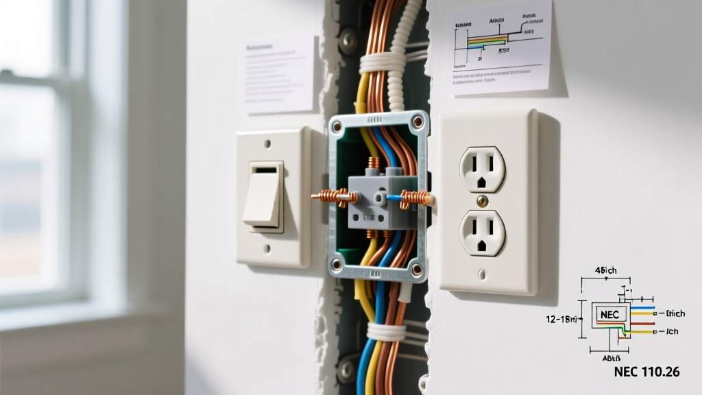

The Anatomy of an Electrical Outlet Type A (NEMA 1-15R)
When working in homes built before the mid-1960s, electricians and DIYers frequently encounter the electrical outlet type A. In North America, this ungrounded, two-prong receptacle is officially classified by the National Electrical Manufacturers Association (NEMA) as the NEMA 1-15R. According to the NEMA WD 6 standard, the Type A configuration features two flat, parallel blades: a narrower hot slot (1/4 inch or 6.3mm wide) and a wider neutral slot (5/16 inch or 7.9mm wide) to enforce polarization.
Rated for 15 Amps at 125 Volts, the Type A outlet lacks the crucial U-shaped equipment grounding conductor (EGC) pin found on modern NEMA 5-15R receptacles. While the National Electrical Code (NEC) mandated grounding for all new branch circuits in 1962 (and extended it to all receptacles in 1971), millions of Type A outlets remain in service today. Upgrading them requires a thorough understanding of ungrounded wiring scenarios, local code compliance, and modern safety devices.
The Hidden Danger: Bootleg Grounds and False Upgrades
Before exploring compliant wiring scenarios, we must address a lethal practice common in amateur flips and unpermitted renovations: the bootleg ground. This occurs when a previous owner replaces a 2-prong Type A receptacle with a modern 3-prong NEMA 5-15R and installs a jumper wire between the neutral (silver) terminal and the ground (green) terminal.
⚠️ Critical Safety Warning: A bootleg ground creates a false sense of security. While a standard 3-light receptacle tester will read "Correct," the ground pin is now energized with the neutral return current. If the neutral wire disconnects anywhere upstream, the metal chassis of any plugged-in appliance will become fully energized at 120V, posing a severe electrocution hazard. The OSHA grounding standards and NEC Article 250 strictly prohibit this practice.
3 Common Wiring Scenarios for Type A Replacement
When you open the wall box behind an electrical outlet type A, the wiring method dictates your upgrade path. Here are the three most common scenarios you will encounter in the field.
Scenario 1: The Metal Conduit (EMT) Ground Path
In many mid-century commercial buildings and some residential builds, Type A outlets were wired using Electrical Metallic Tubing (EMT) or flexible metal conduit (Greenfield). If the metal conduit is continuous and properly bonded all the way back to the main service panel, the metal box and conduit can serve as the Equipment Grounding Conductor (EGC).
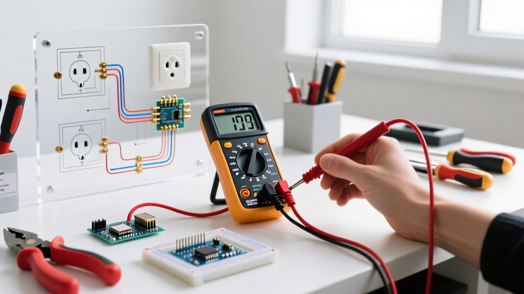
- Testing Protocol: Use a True-RMS multimeter (like the Fluke 117) set to AC Volts. Measure between the hot slot and the metal wall box. If you read ~120V, switch to Ohms (with power OFF) and measure resistance between the box and a known ground at the panel. A reading of less than 2 ohms confirms a solid ground path.
- The Fix: You can legally install a standard grounded NEMA 5-15R receptacle. Ensure you use a grounding pigtail from the receptacle's green screw to the metal box using a 10-32 grounding screw.
Scenario 2: No Equipment Ground (The GFCI Loophole)
This is the most common scenario in older homes with original Knob & Tube or early ungrounded NM (Romex) cloth wiring. There is simply no ground wire, and the box is non-metallic or ungrounded.
Under NFPA 70 (NEC) Article 406.4(D)(2)(b) and 406.4(D)(4), you are permitted to replace an ungrounded Type A receptacle with a Ground Fault Circuit Interrupter (GFCI) receptacle. The GFCI does not create a ground; instead, it monitors the current imbalance between hot and neutral, tripping in milliseconds if a ground fault (current leaking through a person) is detected.
- Required Hardware: A 15A or 20A GFCI receptacle (e.g., Leviton 1599-W or Pass & Seymour 2095-W, typically $18–$26).
- Code Mandate: You must affix the "GFCI Protected" and "No Equipment Ground" stickers included in the receptacle packaging to the faceplate. Surge protectors plugged into this outlet will not function correctly, as they require a true EGC to divert transient voltage.
Scenario 3: Complete Circuit Rewiring
If the homeowner requires true grounding for sensitive electronics, medical equipment, or surge suppression, the only code-compliant solution is to pull new cable. This involves fishing new 14/2 or 12/2 NM-B copper cable from the panel to the outlet locations. Expect to pay licensed electricians between $15 and $28 per linear foot for retrofit rewiring in finished drywall, depending on regional labor rates and attic/crawlspace accessibility.
Step-by-Step: Installing a GFCI on an Ungrounded Type A Circuit
When executing Scenario 2 (GFCI replacement), precision and adherence to torque specifications are vital. NEC 110.14 requires terminal screws to be tightened to the manufacturer's specified torque.
- De-energize and Verify: Turn off the branch circuit breaker. Insert a non-contact voltage tester and a multimeter into the Type A slots to confirm 0V.
- Extract and Inspect: Remove the old receptacle. Inspect the wire insulation. If the cloth or rubber insulation is brittle and flaking, strip it back to fresh copper using a Klein 11048 wire stripper, or apply heat-shrink tubing over the damaged section.
- Identify Line vs. Load: If this is the first outlet on the circuit, use the LINE terminals. If you are protecting downstream outlets, identify the downstream cable and connect it to the LOAD terminals. Note: For a single ungrounded location, only use the LINE terminals.
- Make the Connections: Connect the black (hot) wire to the brass LINE HOT screw. Connect the white (neutral) wire to the silver LINE NEUTRAL screw. Wrap the wire clockwise around the screw so tightening pulls the loop closed.
- Torque to Spec: Using a calibrated torque screwdriver (e.g., Wiha 64504), tighten the terminal screws to 12-14 inch-pounds (verify with the spec sheet on the GFCI box).
- Handle the Missing Ground: Since there is no ground wire, leave the green grounding screw empty. Do not connect it to the neutral.
- Apply Labels and Test: Mount the GFCI, attach the faceplate, apply the mandatory NEC warning stickers, restore power, and press the built-in TEST/RESET buttons to verify mechanical function.
Receptacle Comparison Matrix: Type A vs. Modern Alternatives
| NEMA Configuration | Common Name | Amps / Volts | Grounding | NEC Status (2026) |
|---|---|---|---|---|
| 1-15R | Type A (2-Prong) | 15A / 125V | None | Obsolete; Replacement only |
| 5-15R | Type B (3-Prong) | 15A / 125V | Yes (EGC) | Standard for general use |
| 5-20R | Type B (20A T-Slot) | 20A / 125V | Yes (EGC) | Required in kitchens/baths |
| 6-15R | 250V Receptacle | 15A / 250V | Yes (EGC) | Used for heavy appliances |
Frequently Asked Questions (FAQ)
Can I use a 3-prong to 2-prong "cheater plug" adapter?
Cheater plugs (adapters) are only legal and safe if the metal wall box is genuinely grounded AND you securely attach the adapter's green grounding pigtail to the faceplate's center screw, which must make contact with the grounded metal box. In 95% of older homes with non-metallic boxes or ungrounded conduits, using a cheater plug provides zero grounding protection and violates safety best practices.
Does a GFCI receptacle protect my TV from power surges?
No. A GFCI protects humans from lethal shock by detecting current imbalances (ground faults). It does not protect equipment from voltage spikes. Surge protectors require a true Equipment Grounding Conductor (EGC) to safely divert excess voltage to the earth. Plugging a surge protector into a GFCI-protected but ungrounded Type A circuit leaves your electronics vulnerable to transient overvoltages.
What if the Type A outlet is on a multi-wire branch circuit (MWBC)?
If you discover a shared neutral (two hot wires on different phases sharing one white neutral wire) feeding your old Type A outlets, you must use a 2-pole GFCI breaker in the panel rather than individual GFCI receptacles at the outlet. Standard point-of-use GFCIs will immediately trip on an MWBC due to the shared neutral return current confusing the internal sensing coil.