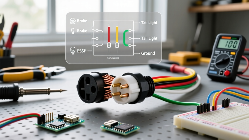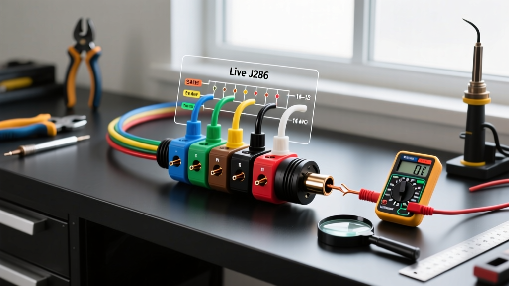

The Anatomy of the SAE J286 7-Way RV Connector
When towing heavy-duty trailers, fifth wheels, or equipment haulers, the 4-way flat connector simply does not provide the necessary circuits for electric brakes, reverse lights, and auxiliary 12V power. This is where the 7-way RV blade connector—governed by the SAE J286 standard—becomes mandatory. Understanding the exact wiring diagram for a 7 wire trailer plug is critical; a single miswired pin can result in blown vehicle fuses, inoperable trailer brakes, or catastrophic electrical fires.
Unlike simple household switches and outlets, trailer wiring operates in a high-vibration, high-moisture environment. In 2026, modern proportional brake controllers (like the Redarc Tow-Pro Elite or Curt Spectrum) draw precise PWM (Pulse Width Modulation) signals, making clean connections and correct wire gauges more important than ever.
Standard 7-Way Pinout Matrix (Clock-Face Orientation)
When looking directly at the vehicle-side socket or the trailer-side plug face, the pins are arranged in a circular pattern. Below is the definitive pinout matrix based on industry standards.
| Pin Position | Function | Vehicle-Side Wire Color | Trailer-Side Wire Color | Min. AWG |
|---|---|---|---|---|
| Center | 12V Auxiliary / Battery Charge | Black | Red or Black | 12 AWG |
| 12 o'clock | Left Turn & Stop | Yellow | Yellow | 16 AWG |
| 2 o'clock | Reverse Lights | Blue or Purple | Blue or Purple | 16 AWG |
| 5 o'clock | Ground (White) | White | White | 10 AWG |
| 7 o'clock | Right Turn & Stop | Green | Green | 16 AWG |
| 9 o'clock | Electric Brakes | Blue | Black or Blue | 12 AWG |
| 10 o'clock | Tail / Running / Marker Lights | Brown | Brown | 16 AWG |
The Danger Zone: Vehicle vs. Trailer Color Crossovers
The most common mistake DIYers make when consulting a wiring diagram for a 7 wire trailer plug is assuming the wire colors match perfectly on both sides of the connection. They do not.
Expert Warning: On the vehicle side, the Blue wire is universally used for Electric Brakes (to match the output of aftermarket brake controllers), while the Black wire is used for 12V Auxiliary power. However, on many pre-wired trailer sides, manufacturers use Black for Electric Brakes and Red for 12V Auxiliary. Always trace the wire to its destination on the trailer rather than trusting the jacket color blindly.
Common Wiring Scenarios and Execution Steps
Scenario A: Hardwiring a New 7-Way Plug to an Existing 4-Way Harness
If your truck has a 4-way flat and you need to tow a trailer with electric brakes, you must upgrade the vehicle side. Do not rely solely on plug-and-play adapters for heavy loads; hardwiring ensures voltage stability.
- Tap the 4-Way: Connect the White (Ground), Brown (Tail), Green (Right), and Yellow (Left) wires from your new 7-way pigtail to the corresponding 4-way wires using heat-shrink butt connectors.
- Route the Brake Wire: Run a dedicated 12 AWG Blue wire from the 7-way plug directly to the output terminal of your brake controller under the dash. Do not splice into existing taillight circuits.
- Run the 12V Aux Line: Run a 12 AWG Black wire from the 7-way plug to the vehicle battery. Crucial: Install a 30-amp inline circuit breaker within 18 inches of the battery positive terminal to prevent fires in case of a dead short.
- Secure the Ground: The 10 AWG White ground wire must be attached to a clean, bare-metal chassis point. Use a star washer to bite through paint and rust, ensuring a resistance of less than 0.1 ohms to the battery negative terminal.
Scenario B: Replacing a Corroded Trailer-Side Molded Plug
Molded 7-way plugs often fail internally due to water ingress. When cutting off a molded plug to install a screw-terminal replacement (like the Pollak 7-Pole Round Pin to 7-Way Blade Adapter), you will encounter a bundle of wires encased in thick rubber.
- Strip back at least 3 inches of the outer rubber jacket.
- Use a wire brush to clean the copper strands; corrosion often wicks up inside the insulation.
- Apply a marine-grade heat shrink tube over each terminal connection. Standard vinyl electrical tape will peel off within months due to UV exposure and road vibration.
Wire Gauge, Voltage Drop, and Long-Trailer Math
A frequent failure mode in 30+ foot trailers is dim running lights or weak electric brake engagement. This is caused by voltage drop. According to standard electrical principles and resources like the Southwire Voltage Drop Calculator, a 16 AWG copper wire carrying 5 amps over a 60-foot round trip (30 feet to the back of the trailer and 30 feet back to ground) will experience a voltage drop of over 1.5 volts. This leaves your 12V LED markers running at 10.5V, causing flickering.
The Fix: For trailers exceeding 25 feet in length, upgrade the Brown (Tail/Marker) circuit from 16 AWG to 14 AWG. Furthermore, ensure the White ground wire is a full 10 AWG. Many cheap replacement pigtails use 12 AWG for the ground to save copper costs; this creates a bottleneck for the entire lighting system since all return current flows through this single pin.
Troubleshooting Edge Cases and Failure Modes
Even with a perfect wiring diagram for a 7 wire trailer plug, environmental factors cause unique electrical gremlins. Here is how to diagnose the three most common 7-way failures:
1. 'Ghost Braking' and Backfeed
Symptom: The trailer brakes engage slightly when you turn on the vehicle's headlights, or the brake controller shows a constant low-level draw even when the pedal is untouched.
Cause: Moisture inside the 7-way plug creates a conductive bridge between the 12V Aux pin (Center) and the Electric Brake pin (9 o'clock). The 12V charge line backfeeds into the brake circuit.
Solution: Disassemble the plug, clean the pins with electrical contact cleaner, and apply a thin layer of only on the outer rubber boot. Never pack dielectric grease inside the pin cavities—it is an insulator and will block the PWM brake signal.
2. The 'Blinker Hyper-Flash' on the Tow Vehicle
Symptom: When the trailer is plugged in, the truck's turn signals blink twice as fast.
Cause: A poor ground connection on the trailer side forces the turn signal current to seek an alternative ground path, often backfeeding through the running light circuit. This alters the resistance the truck's flasher relay detects.
Solution: Do not just replace the flasher relay. Run a dedicated 10 AWG ground wire from the trailer plug directly to the trailer tongue, bypassing the hinge and safety chain connections entirely.
3. Blown Vehicle Fuses Upon Connection
Symptom: Plugging in the trailer immediately blows the 15A 'Trailer Tow' fuse in the truck's under-hood PDC (Power Distribution Center).
Cause: A crushed wire on the trailer's running gear or a corroded marker light housing where the 12V hot wire is touching the metal frame.
Solution: Use a digital multimeter set to continuity mode. Disconnect the trailer plug and test the resistance between the Brown (Tail) pin and the White (Ground) pin. It should read 'OL' (Open Loop). If it reads near 0 ohms, you have a dead short on the trailer's marker light circuit that must be isolated.
Expert Terminating and Weatherproofing Standards
When terminating the wires into a screw-terminal 7-way plug, the physical connection is just as vital as the schematic. For compliance with best practices outlined in RV and towing safety guidelines (often referenced alongside NFPA 70 / NEC Article 551 regarding RV park and vehicle electrical safety), follow these terminal rules:
- Use Ferrules or Spade Lugs: Do not wrap bare stranded wire around a screw terminal. Vibration will cause the strands to splay, creating a high-resistance hot spot. Crimp on insulated spade terminals or wire ferrules before securing them under the terminal screws.
- Torque Specifications: Tighten terminal screws to roughly 12-15 in-lbs. Overtightening will snap the brass terminal post; undertightening will cause arcing.
- Strain Relief: Ensure the outer cable jacket is clamped securely by the plug's internal cord grip. If individual colored wires are bearing the physical pulling weight of the plug, the copper strands will eventually fatigue and snap.
For further reading on complex towing setups, including integrating 7-way plugs with modern CAN-bus vehicle networks, consult the comprehensive guides available at etrailer's Wiring FAQ. Mastering the 7-way plug ensures your rig remains safe, legal, and fully functional on the road.