
The Thermodynamics of a Failing Receptacle
When an electrical outlet gets hot to the touch, it is no longer a passive conduit for electricity; it has become a resistor. According to Joule's First Law of heating, thermal energy generated in a conductor is proportional to the square of the current multiplied by the resistance ($P = I^2R$). In a properly wired 120V, 15-amp or 20-amp branch circuit, the resistance at the termination points should be near zero. However, when wiring diagram specifications are ignored—resulting in loose connections, degraded internal contacts, or improper daisy-chaining—resistance spikes. This localized resistance converts electrical energy into dangerous heat, often pushing faceplate temperatures past 140°F, well into the deformation zone of standard PVC wire insulation.
According to the National Fire Protection Association (NFPA), electrical distribution and lighting equipment consistently rank among the leading causes of residential structure fires. Understanding how to read and correct wiring diagrams is your first line of defense against thermal runaway.
Common Wiring Diagram Errors That Cause Overheating
Most thermal failures at the receptacle level stem from three specific deviations from standard NEC-compliant wiring diagrams.
1. The "Backstab" Push-In Connection Failure
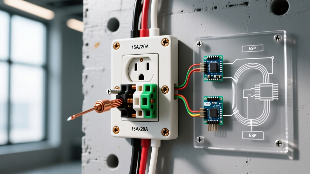
Standard builder-grade receptacles feature quick-wire push-in terminals on the back. While NEC permits these for 14 AWG solid copper wire, they rely on a small internal spring-clip to maintain contact pressure. Under continuous loads exceeding 10 amps (such as space heaters or window AC units), thermal cycling causes the spring metal to fatigue and lose tension. The resulting micro-arcing and increased contact resistance generate intense, localized heat that melts the polycarbonate housing. Correction: Always use the side-binding screw terminals, wrapping the wire clockwise around the screw so that tightening the screw pulls the loop closed.
2. Loose Shared Neutral in Multi-Wire Branch Circuits (MWBC)
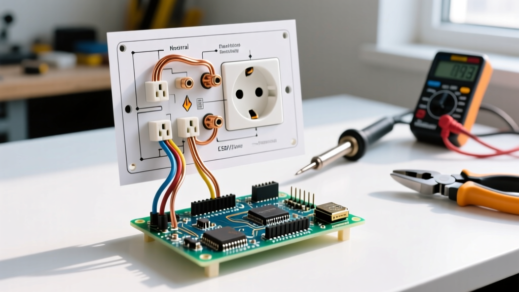
An MWBC uses two hot wires (on opposite phases) sharing a single neutral wire. If a DIYer misinterprets the wiring diagram and fails to secure the shared neutral, or if the neutral pigtail is disconnected while the circuit is energized, the 120V appliances on both legs effectively become wired in series across 240V. This causes massive current imbalances, severe overheating of the neutral terminal, and catastrophic appliance failure. Correction: NEC requires simultaneous disconnection of all ungrounded conductors in an MWBC. Use a 2-pole breaker and ensure the neutral pigtail is torqued to spec.
3. Pass-Through Overloading (Failing to Pigtail)
When daisy-chaining outlets, running the incoming hot/neutral to one set of screws and the outgoing hot/neutral to the second set forces the receptacle's internal brass strap to carry the cumulative load of all downstream devices. If the downstream load is 12A and the local load is 6A, the internal strap carries 18A. On a 15A receptacle, this guarantees overheating. Correction: Use Wago 221-413 lever nuts or Ideal 341 wire nuts to create pigtails, ensuring the receptacle only carries its own local load.
Heat Signature Diagnostic Matrix
Use an infrared thermometer or thermal camera to map the heat signature. The location of the hot spot directly correlates to specific wiring diagram faults.
| Thermal Reading | Location of Heat | Probable Wiring Fault | Diagram Correction |
|---|---|---|---|
| 110°F - 130°F | Top or Bottom edge (near screws) | Loose side-terminal screw or backstabbed wire fatigue. | Strip wire to 3/4", wrap clockwise, torque to 14 in-lbs. |
| 130°F - 150°F | Center of the faceplate | Internal brass strap overload (pass-through wiring without pigtails). | Install wire nut pigtails for both line and load sides. |
| >150°F | Entire faceplate / Wall cavity warmth | Shared neutral failure (MWBC) or severe ground fault arcing. | Verify 2-pole breaker, check neutral continuity, inspect for scorch marks. |
Step-by-Step Termination and Torque Specifications
To eliminate high-resistance connections, professional electricians adhere to strict termination protocols. The Consumer Product Safety Commission (CPSC) emphasizes that proper installation is critical to preventing electrical fires.
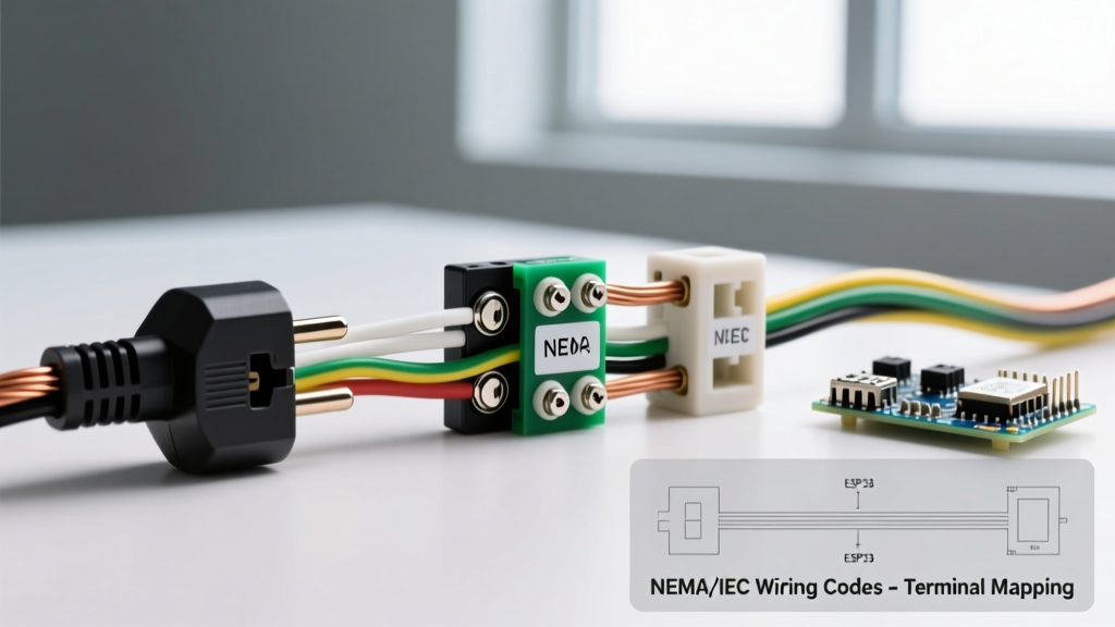
- Strip to Exact Gauge: Use a precision stripper (like the Klein 11055) to strip exactly 3/4 inch of insulation from 12 AWG or 14 AWG solid copper. Exposed copper should not extend past the screw head, which creates a short-circuit hazard.
- Form the Hook: Use needle-nose pliers to form a tight, 270-degree hook. The hook must enter the terminal from the bottom-left so the screw's clockwise rotation pulls the wire tighter.
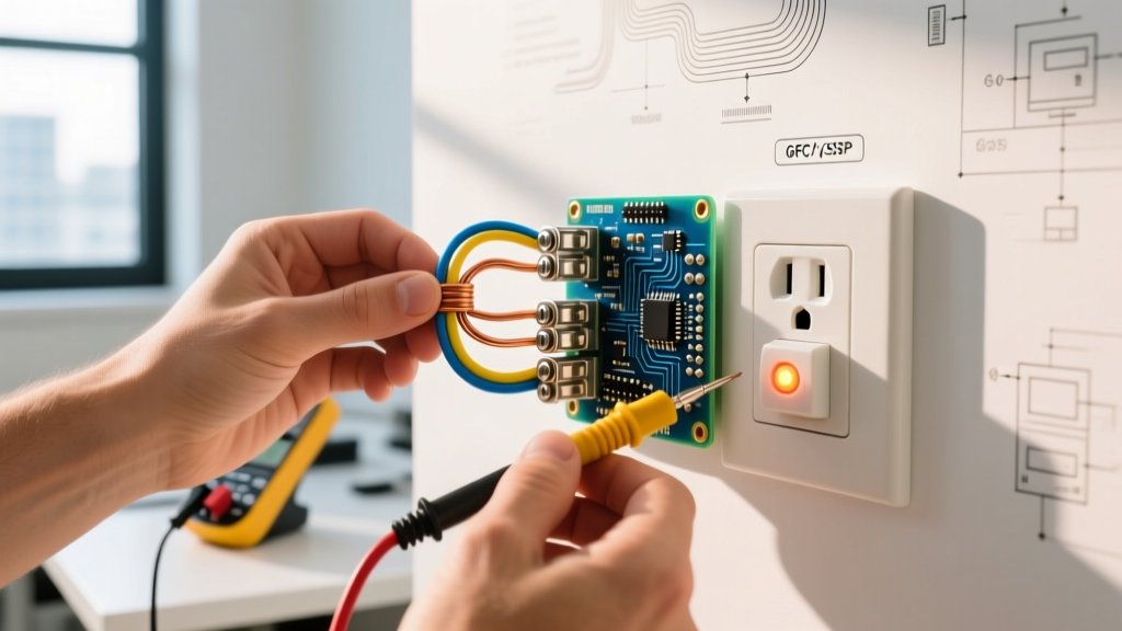
- Apply Calibrated Torque: NEC 110.14(D) mandates the use of a calibrated torque tool. For standard Leviton and Hubbell 15A/20A receptacles, the manufacturer specification is typically 14 in-lbs. Use a torque screwdriver (e.g., Klein Tools 32500) to ensure the screw is neither under-tightened (causing arcing) nor over-tightened (stripping the brass threads or snapping the wire).
Upgrading to High-Heat Tolerance Receptacles
If your wiring diagram is correct but the environment demands heavy continuous loads (e.g., a dedicated workshop circuit or a kitchen appliance garage), upgrade the hardware. Not all receptacles are built with the same thermal thresholds.
- Builder-Grade (e.g., Leviton T5262): Costs ~$1.29. Uses standard thermoplastic. Internal contacts are thin brass. Prone to heat deformation under continuous 12A+ loads.
- Spec-Grade (e.g., Leviton 5262-SW or Hubbell 5262-I): Costs ~$4.50 to $6.00. Features high-impact nylon or urea-formaldehyde thermoset housings that resist melting up to much higher temperatures. Internal contacts utilize thicker, beryllium-copper alloys for superior spring tension and lower resistance.
- Hospital-Grade (e.g., Hubbell 5362): Costs ~$12.50+. Designed for extreme durability and continuous high-load reliability. Features oversized termination screws and the highest grip-force on the grounding and neutral blades.
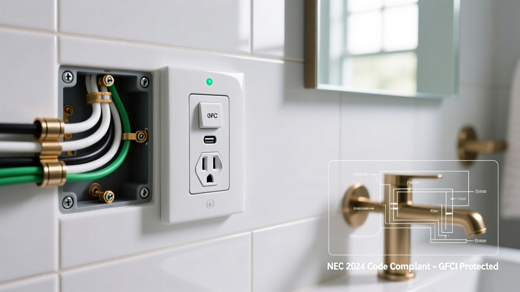
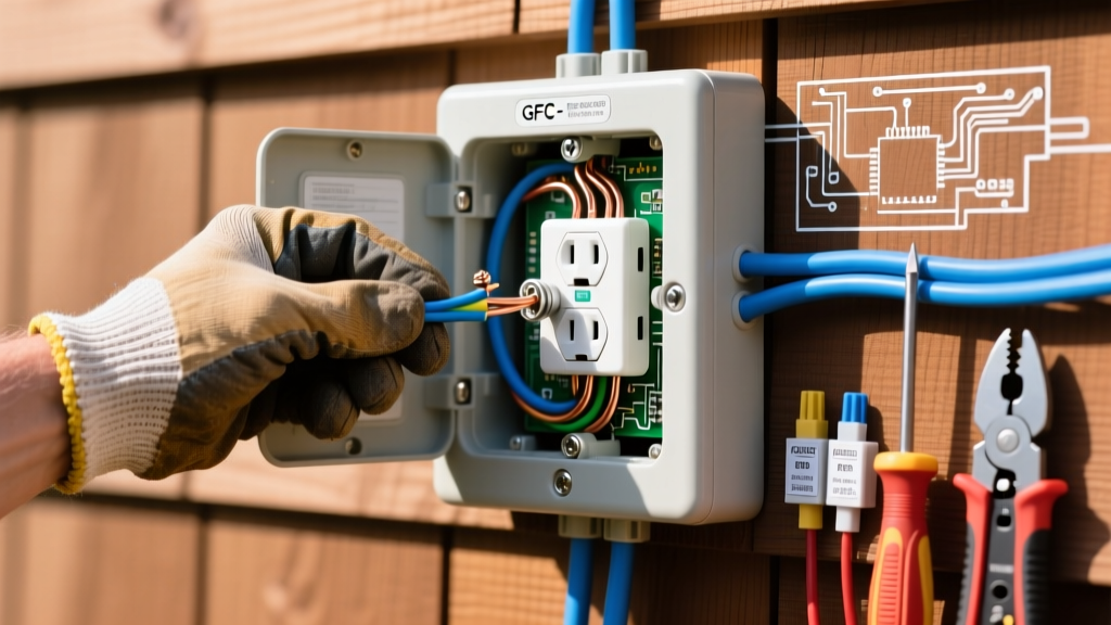
Expert Note on GFCI Thermal Issues: If a GFCI outlet gets hot specifically around the "Test/Reset" buttons, the solid-state sensing circuitry is likely failing or overheating due to a reversed Line/Load wiring error. While a reversed GFCI will still power downstream outlets, it bypasses the internal thermal and fault-protection logic, leading to dangerous heat buildup in the microprocessor housing. Always verify Line (source) and Load (downstream) using a non-contact voltage tester before termination.
Final Safety and Code Compliance
An electrical outlet that gets hot is a symptom of a systemic wiring failure, not an isolated anomaly. Always shut off the breaker, verify zero voltage with a CAT III multimeter, and inspect the wire insulation for brittleness or charring. If the PVC insulation has melted back more than 1/4 inch past the wire nut or terminal, the wire must be cut back to clean, unoxidized copper. For further reading on residential electrical safety standards and fire prevention, consult the Electrical Safety Foundation International (ESFI) guidelines on outlet maintenance and circuit loading.