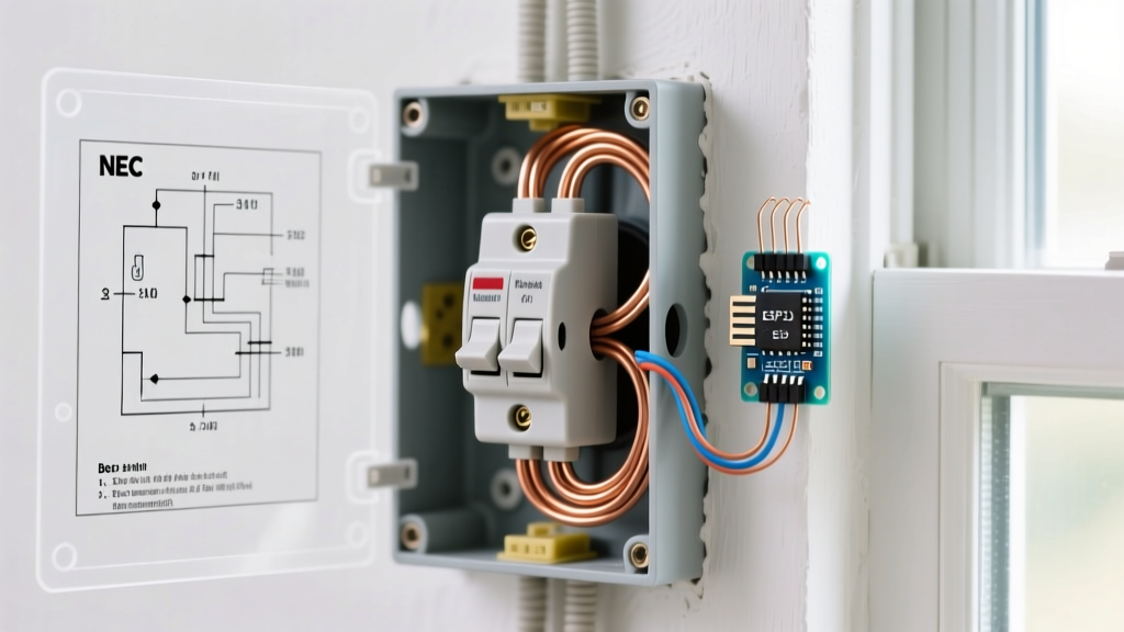

Bridging Visual Planning and Physical Electrical Upgrades
When homeowners, DIY electricians, and home inspectors search for electrical outlet clipart, they are typically looking for visual symbols to map out a renovation, create a digital home manual, or design a smart home dashboard. However, finding the right 2D vector graphics is only the first step. Translating those symbols into a physical, code-compliant receptacle upgrade requires a deep understanding of the National Electrical Code (NEC) and modern wiring practices.
As of 2026, replacing outdated, ungrounded, or standard 15A duplex receptacles with modern Tamper-Resistant (TR), GFCI, AFCI, and USB-C integrated models is one of the highest-ROI electrical upgrades you can perform. This guide will show you how to use electrical symbols and clipart to audit your home, create an actionable shopping list, and execute the physical replacements safely and to code.
Decoding Electrical Outlet Clipart and NEC Symbols
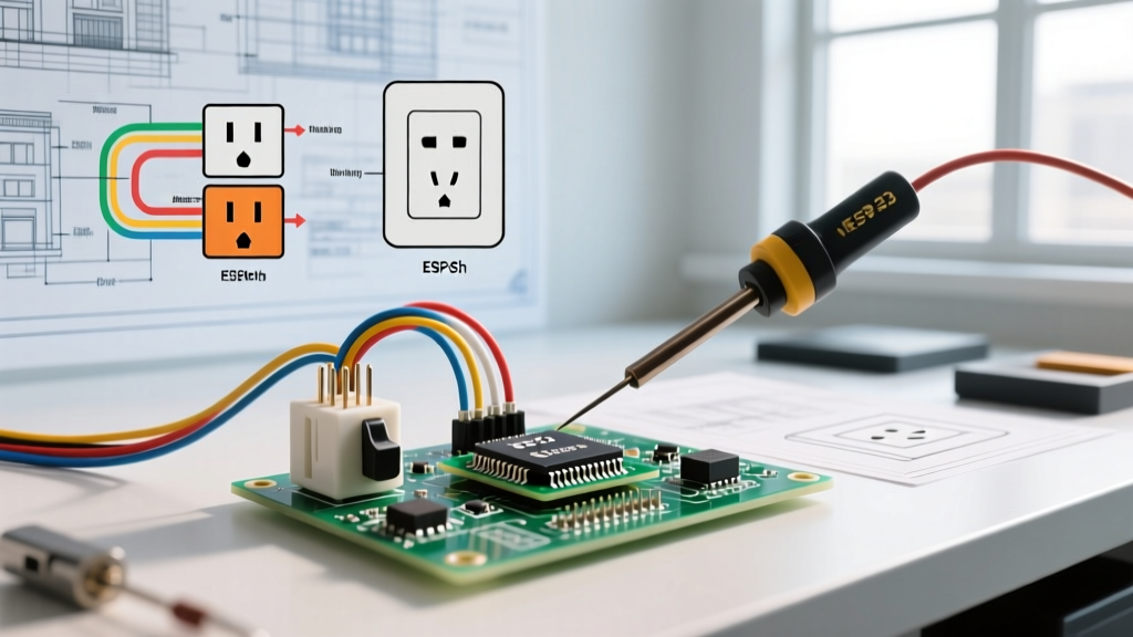
Professional electricians do not use generic clipart; they use standardized architectural symbols defined by the American National Standards Institute (ANSI) and referenced in NEC documentation. When drawing your floor plan, use this matrix to ensure your visual map aligns with the physical components you need to purchase.
| Visual Symbol (Clipart Equivalent) | NEC / ANSI Designation | 2026 Upgrade Equivalent (Physical Product) | Average Cost (Per Unit) |
|---|---|---|---|
| Circle with two parallel lines | Standard Duplex Receptacle | Leviton 2095TR (15A Tamper-Resistant) | $3.50 - $5.00 |
| Circle with 'GF' inside | Ground Fault Circuit Interrupter | Eaton GFTR15W (15A GFCI TR) | $16.00 - $22.00 |
| Circle with 'AF' or arc symbol | Arc Fault Circuit Interrupter | Receptacle fed by AFCI Breaker (e.g., Eaton BR115AF) | $45.00+ (Breaker) |
| Circle with USB / Type-C icon | USB Charging Receptacle | Leviton T5636 (Type-C / Type-A USB, 15A TR) | $28.00 - $34.00 |
| Circle with isolated ground symbol (Triangle) | Isolated Ground (IG) Receptacle | Hubbell 5262IG (15A Duplex IG) | $12.00 - $15.00 |
Step-by-Step Receptacle Upgrade Planning
Before buying a single outlet or turning off a breaker, you must map your circuits. Using your electrical outlet clipart library, print a floor plan of your home and follow this audit process:
1. Identify the Kitchen and Bathroom Zones
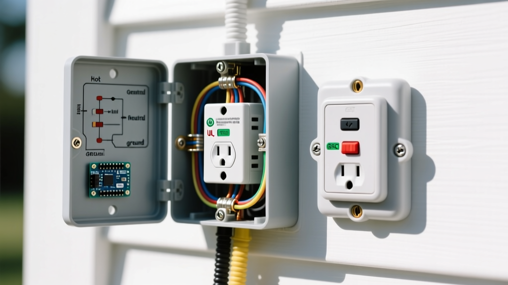
Per NEC Article 210.8, all 125-volt, 15- and 20-ampere receptacles installed in kitchens and bathrooms must have GFCI protection. Mark every outlet within 6 feet of a sink on your floor plan with the 'GF' symbol. Upgrade Note: If you are upgrading a kitchen countertop, NEC 210.52(C) requires that no point along the wall line is more than 24 inches from a receptacle. Ensure your symbol map reflects this spacing.
2. Map the Living Areas for AFCI Compliance
NEC Article 210.12 mandates Arc-Fault Circuit Interrupter (AFCI) protection for all 120V, 15A and 20A branch circuits supplying outlets in dwelling unit living rooms, bedrooms, and hallways. While AFCI protection is usually handled at the breaker panel, mapping these circuits on your floor plan ensures you do not accidentally install a GFCI receptacle on an AFCI breaker circuit in a way that causes nuisance tripping (a common issue known as 'stacking' fault protection).
3. Plan for High-Density Charging Zones
In 2026, the proliferation of USB-C PD (Power Delivery) devices means standard 5W USB outlets are obsolete. Mark your nightstands, kitchen islands, and home office desks with the USB-C symbol. When purchasing, look for models like the Leviton T5636, which delivers up to 30W of shared power via USB-C, capable of fast-charging modern laptops and smartphones simultaneously.
The Physical Replacement Guide: Wiring the Upgrades
Once your visual map is complete and materials are sourced, it is time to execute the physical replacement. The most common upgrade is swapping a standard 15A duplex for a GFCI or USB receptacle.
Safety Warning: Always verify the circuit is de-energized using a non-contact voltage tester (e.g., Klein Tools NCVT-2) and a multimeter before touching any terminals. Never rely solely on a wall switch to isolate power.
Wiring a GFCI Receptacle (Line vs. Load)
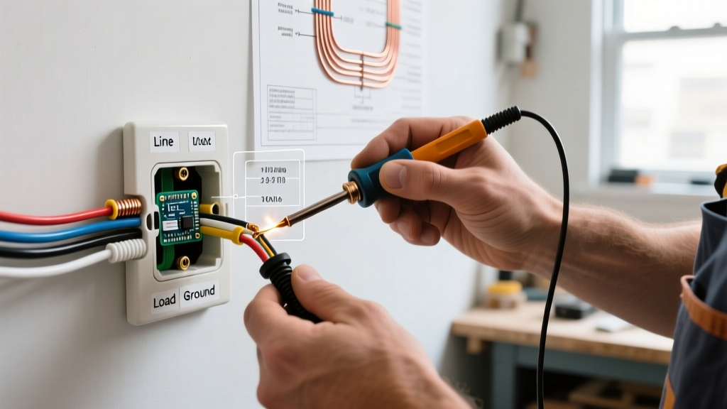
The most frequent mistake DIYers make when upgrading to a GFCI is misidentifying the LINE and LOAD terminals. The GFCI receptacle has two distinct sets of screws, often covered by a yellow warning tape from the factory.
- Identify the Line: The LINE terminals connect to the incoming power from the breaker panel. Use a voltage tester to confirm which black (hot) and white (neutral) wires are live before turning off the power.
- Connect the Line: Strip 3/4 inch of insulation. Insert the bare copper into the LINE terminal holes and tighten the screws.
- Connect the Load (Downstream Protection): If your floor plan map shows additional standard outlets downstream that need GFCI protection, connect their incoming wires to the LOAD terminals. If not, leave the LOAD terminals empty and cap the wires.
- Grounding: Connect the bare copper or green ground wire to the green grounding screw. If the metal box is grounded, run a 14 AWG copper pigtail from the box's ground clip to the receptacle's ground screw.
The Torque Requirement (NEC 110.14(D))
As enforced in recent NEC cycles and strictly monitored by inspectors in 2026, you must use a calibrated torque screwdriver for all terminal connections. Most 15A and 20A receptacles require between 14 in-lbs and 16 in-lbs of torque. Under-torquing causes high-resistance connections, leading to thermal expansion, arcing, and eventual fire. Over-torquing strips the brass terminal plates.
Expert Troubleshooting & Edge Cases
When upgrading older homes (pre-1980s), your physical reality will rarely match your initial electrical outlet clipart map perfectly. Be prepared for these common edge cases:
- The Bootleg Ground: Older 2-prong outlets are sometimes illegally upgraded to 3-prong outlets by jumpering the neutral terminal to the ground screw. This creates a lethal shock hazard if the neutral ever opens. Solution: Remove the jumper. If no true equipment grounding conductor exists, NEC 406.4(D)(2) allows you to install a GFCI receptacle and label it 'No Equipment Ground'. The GFCI will still protect against shock, even without a ground wire.
- Multi-Wire Branch Circuits (MWBC): If you open a junction box and find two hot wires (usually black and red) on different phases sharing a single white neutral wire, you have an MWBC. Solution: Do not install a standard GFCI receptacle here without pigtailing the neutral, or you will cause an immediate trip and potential neutral overload. Use a 2-pole AFCI/GFCI breaker at the panel instead.
- Reverse Polarity: If your receptacle tester shows 'Reverse Polarity' after an upgrade, the hot and neutral wires are swapped. This is common in old cloth-wired homes where wire colors have faded. Use a multimeter to test between the suspected hot wire and a known ground (like a metal water pipe) to identify the true line conductor.
Creating Your As-Built Electrical Directory
The final step of any professional upgrade is updating the documentation. Take your annotated floor plan—complete with all the electrical outlet clipart and symbols you placed during the audit—and digitize it. Create a master PDF or smart home dashboard layer that maps exactly which breaker controls which upgraded GFCI or USB zone. This 'as-built' directory is invaluable for future troubleshooting, home inspections, and emergency shutoffs, bridging the gap between simple visual planning and expert-level electrical execution.
Authoritative References
For further reading on code compliance and safety standards, consult the following resources: