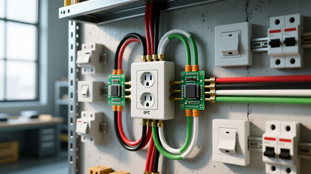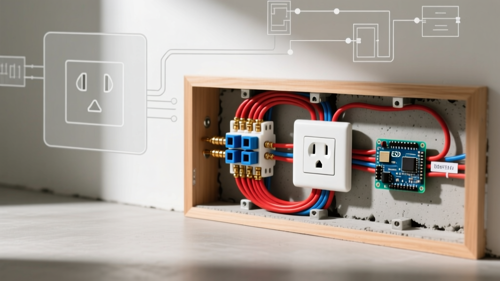

Understanding Electrical Floor Outlet Wiring and NEC Compliance
Installing an electrical floor outlet is one of the most demanding receptacle projects in residential and commercial wiring. Unlike standard wall outlets, floor receptacles are subjected to unique mechanical stresses, foot traffic, and the constant threat of liquid ingress from mopping or spills. Because of these hazards, you cannot simply mount a standard wall box flush with the floor. The National Electrical Code (NEC) mandates specific listed assemblies to ensure safety.
According to National Fire Protection Association (NFPA 70), specifically NEC Article 314.27(B), floor boxes must be listed for the purpose. Furthermore, NEC 406.9(E) dictates that receptacles installed in floor boxes must be part of a listed floor box assembly. Standard wall plates and mud rings are strictly prohibited in floor applications due to the risk of physical damage and shock hazards.
This wiring diagram reference covers the exact schematics, hardware selections, and installation procedures for both wood-framed floors and concrete slab foundations, ensuring your installation is safe, code-compliant, and built to last.
Hardware Selection: Matching the Box to the Subfloor
Before pulling any wire, you must select the correct floor box assembly. The structural composition of your floor dictates the hardware.
- Wood-Framed Floors (Retrofit & New): Use non-metallic old-work boxes like the Carlon B114R (approx. $45) or metallic pancake boxes like the Hubbell HBL6000 series (approx. $180) if surface-mounted on a shallow subfloor.
- Concrete Slab Floors: Use adjustable cast-iron or heavy-duty PVC concrete floor boxes, such as the Steel City 6000 Series or Hubbell SystemOne (ranging from $150 to $300+ depending on gang count and cover style).
- Receptacles: Always use 20-Amp Tamper-Resistant (TR) receptacles. For added moisture protection, upgrade to a Weather-Resistant (WR) model like the Leviton 5362-WR ($8), which features nickel-plated brass straps to resist corrosion from floor cleaning chemicals.
Wiring Diagram 1: Wood-Framed Floor (120V 20A Circuit)
This schematic applies to homes with crawlspace or basement access beneath a wood subfloor. We will use 12/2 NM-B (Romex) cable on a dedicated 20-amp breaker.
Step-by-Step Wiring Schematic
- Locate and Cut: Use a stud finder to ensure you are not cutting through a floor joist. Mark the center of the joist bay and use a 4-inch hole saw to drill through the hardwood and subfloor.
- Run the Cable: Fish the 12/2 NM-B cable from the breaker panel or upstream junction box through the floor cavity. Per NEC 334.30, the cable must be secured within 8 inches of the floor box.
- Prepare the Wires: Strip the outer yellow jacket, leaving exactly 3/4 inch of insulation on the individual black, white, and bare copper conductors. Use a wire stripping tool calibrated for 12 AWG to avoid nicking the copper.
- Grounding First: Connect the bare copper ground wire to the green grounding pigtail provided with the Carlon box, or directly to the green grounding screw on the metallic Hubbell box. Expert Tip: Use a torque screwdriver set to 14 in-lbs to ensure a secure mechanical bond without stripping the screw.
- Terminate Hot and Neutral: Connect the black (hot) wire to the brass terminal screw and the white (neutral) wire to the silver terminal screw on the 20A TR receptacle. Do not use the back-stab push-in connectors; always use the side terminal screws or a pigtail with a wire nut for superior conductivity and heat dissipation.
- Secure and Seal: Push the receptacle into the box, secure it with the provided mounting screws, and attach the gasketed floor cover plate. Ensure the cover sits perfectly flush with the finished floor to prevent tripping hazards.
Wiring Diagram 2: Concrete Slab Floor (PVC Conduit Sweep)
Wiring an electrical floor outlet in a concrete slab requires pre-planning during the foundation pour, or extensive core drilling for retrofits. This diagram utilizes 12 AWG THHN/THWN individual conductors pulled through 1-inch PVC conduit.
Pre-Pour Stub-Up Schematic
- Trench and Sweep: Before the concrete is poured, trench the gravel base. Run 1-inch Schedule 40 PVC conduit from the nearest junction box or panel. Use a long-sweep 90-degree PVC fitting to create the vertical stub-up where the floor box will sit.
- Cap and Protect: Glue a red PVC cap onto the top of the stub-up to prevent concrete slurry from entering the conduit during the pour. Tie the conduit securely to the rebar grid using UV-resistant zip ties or galvanized masonry wire.
- Post-Pour Core Drilling (Retrofit Only): If retrofitting, rent a rotary hammer drill with a 4-inch to 6-inch diamond core bit. Drill through the concrete slab, then use a demo hammer to chisel out a cavity large enough to accommodate the concrete floor box and its conduit hub.
- Pull the Conductors: Use a fiberglass fish tape to pull three 12 AWG THHN wires (Black, White, Green) through the PVC conduit. Leave at least 8 inches of slack inside the floor box cavity.
- Terminate: Wire the receptacle identically to the wood-floor diagram (Black to Brass, White to Silver, Green to Ground). Ensure the grounding wire is also bonded to the internal grounding lug of the cast-iron concrete box.
Installation Matrix: Wood vs. Concrete Subfloors
| Feature | Wood-Framed Floor | Concrete Slab Floor |
|---|---|---|
| Primary Box Type | Carlon B114R (Non-Metallic Old Work) | Steel City / Hubbell Cast-Iron Adjustable |
| Wiring Method | 12/2 NM-B (Romex) | 12 AWG THHN in 1' PVC Conduit |
| Avg. Material Cost | $55 - $85 | $180 - $350+ |
| Installation Time | 1.5 - 2 Hours | 4 - 8 Hours (including core drilling) |
| Moisture Risk | Low (unless ground floor without vapor barrier) | High (wicking from slab requires gaskets) |
Critical Edge Cases: Moisture, GFCI, and Vacuum Pulls
When wiring an electrical floor outlet, standard wall-outlet logic will lead to failure. You must account for the unique environmental factors present at floor level.
The 'Mop Water' Problem and GFCI Nuisance Tripping
Floor outlets are highly susceptible to liquid ingress from routine mopping or accidental spills. If moisture enters the box, it can bridge the gap between the hot terminal and the grounded metal box, causing a short circuit or nuisance tripping if the circuit is GFCI protected.
Expert Solution: Never rely solely on the receptacle's internal contacts to resist corrosion. Always install a Weather-Resistant (WR) receptacle inside the floor box. Furthermore, ensure the floor box cover plate features a neoprene or silicone O-ring gasket. If the floor outlet is in a commercial kitchen or wet area, NEC Article 406.9(E) requires the entire assembly to be listed for wet locations, which often necessitates a specialized 'flip-cover' or 'pop-up' floor box with a watertight seal when closed.
Mechanical Stress from Vacuum Cleaners and Carts
Unlike wall outlets where cords hang vertically, floor outlet cords run horizontally across the floor. This creates severe mechanical leverage on the receptacle face whenever a vacuum cleaner, rolling cart, or heavy foot catches the cord.
- Failure Mode: The internal brass contacts of the receptacle spread apart, leading to a loose neutral connection. A loose neutral causes arcing, extreme heat, and ultimately melts the receptacle face or starts a fire.
- Prevention: Use a floor box cover plate equipped with a cord grip or cord protector (such as the Hubbell HBL6000 series covers). These covers feature a built-in clamp that secures the plug head, transferring the physical pulling force away from the receptacle's internal terminals and onto the heavy-duty metal cover plate.
Safety and Inspection Guidelines
Before energizing the circuit, perform a thorough visual and mechanical inspection. Verify that no bare copper ground wires are touching the brass hot terminals. Ensure the receptacle is seated firmly against the box mounting ears with no gaps. According to the Occupational Safety and Health Administration (OSHA), improper grounding and loose connections are leading causes of electrical fires in commercial spaces.
Finally, test the receptacle with a digital multimeter to confirm 120V (+/- 5%) between hot and neutral, and near 0V between neutral and ground. Once verified, apply the final cover plate, ensuring all screws are tightened evenly to compress the gasket uniformly. For more information on product safety listings, always verify your floor box assembly carries a valid Underwriters Laboratories (UL) Electrical Safety mark specifically for floor applications.