
Core Principles of Electric Switch Wiring
Understanding electric switch wiring requires more than just connecting black to black and white to white. Modern residential and commercial electrical systems demand strict adherence to the National Electrical Code (NEC), particularly regarding neutral wire retention, grounding continuity, and arc-fault protection. Whether you are upgrading a standard toggle to a smart dimmer or mapping out a multi-location hallway circuit, this wiring diagram reference provides the exact topologies, wire gauges, and terminal configurations required for safe, code-compliant installations in 2026.
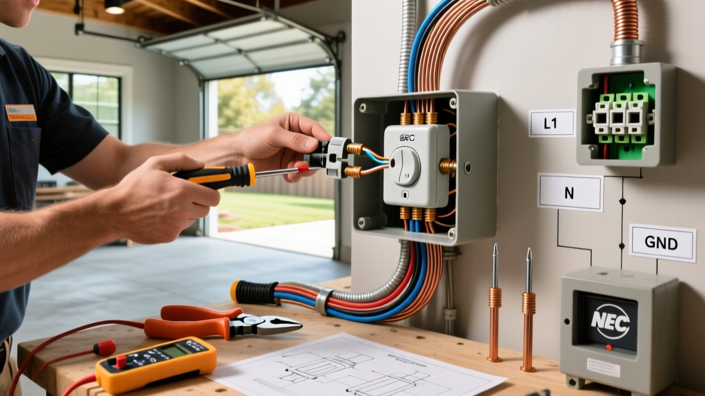
Safety Warning: Always de-energize the circuit at the main breaker panel and verify zero voltage using a Category III or IV True-RMS multimeter before opening any junction box. The Occupational Safety and Health Administration (OSHA) reports that improper lockout/tagout and failure to verify dead circuits are leading causes of residential and commercial electrical injuries.
Single-Pole Switch Wiring: The Baseline Topology
The single-pole switch is the most common configuration, controlling a lighting load from a single location. In a standard 120V AC branch circuit, the power source (line) enters the switch box, and the switched leg (load) exits to the fixture.
Terminal & Wire Mapping
- Line (Hot): Black wire from the 14/2 or 12/2 NM-B supply cable connects to the bottom brass terminal.
- Load (Switched Hot): Black wire leading to the light fixture connects to the top brass terminal.
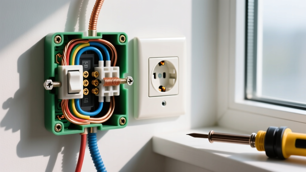
- Neutral: White wires are spliced together with a wire nut (or WAGO 221 lever nut) and pushed to the back of the box. Note: NEC 2023/2026 Article 404.2(C) requires a neutral conductor to be present at the switch box for future smart switch compatibility, even if the current mechanical switch does not use it.
- Ground: Bare copper or green insulated wires are pigtailed to the green grounding screw on the switch yoke and the metal box (if applicable).
3-Way Switch Wiring Configurations
A 3-way circuit allows control of a single load from two distinct locations (e.g., top and bottom of a stairwell). This requires two 3-way switches (such as the Leviton Decora 15A, Model R62-05603-2WS) and a 3-conductor cable (14/3 NM-B) running between them.
The Traveler Matrix
Unlike single-pole switches, 3-way switches feature one common terminal (usually a dark-colored screw) and two traveler terminals (brass screws). The wiring logic depends on where the power source originates:
- Power at Switch 1: The line hot connects to the common screw on Switch 1. The 14/3 cable carries the two travelers (red and white, re-marked with black tape) to Switch 2. The common screw on Switch 2 feeds the load to the light fixture.
- Power at the Fixture: The line hot drops to the light box. A 14/2 cable carries the permanent hot down to Switch 1's common terminal. The 14/3 travelers run between Switch 1 and Switch 2. Switch 2's common terminal sends the switched hot back up to the fixture via the white wire of the 14/2 (re-marked as hot).
4-Way Switch Wiring: Intermediate Control
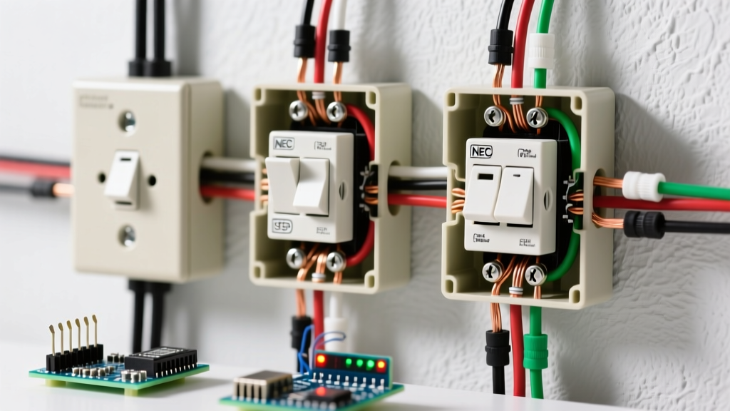
When control from three or more locations is required, a 4-way switch is inserted between two 3-way switches. The 4-way switch (e.g., Leviton Model R62-05604-2WS) acts as a reversing crossover mechanism for the traveler wires.
Wiring the 4-Way Intermediate
The 4-way switch has four terminals, typically divided into two pairs (often labeled 'Line 1' and 'Line 2' or color-coded). The travelers from the first 3-way switch connect to one pair, and the travelers continuing to the second 3-way switch connect to the other pair. Never connect a line hot or a load wire directly to a 4-way switch; it must only interrupt the traveler path.
Wire Gauge, Breaker Sizing, and 2026 Material Costs
Selecting the correct Non-Metallic (NM) sheathed cable is critical for preventing voltage drop and thermal overload. Below is the standard reference for residential lighting circuits.
| Circuit Rating | Wire Gauge (NM-B) | Breaker Type | Max Continuous Load | Est. 2026 Cost per 250ft Spool |
|---|---|---|---|---|
| 15 Amp | 14 AWG (14/2, 14/3) | 15A AFCI | 1,440 Watts (12A) | $115 - $135 |
| 20 Amp | 12 AWG (12/2, 12/3) | 20A AFCI | 1,920 Watts (16A) | $160 - $195 |
Note: Copper pricing fluctuations in late 2025 have stabilized, but local supply house premiums may apply. Always use AFCI (Arc-Fault Circuit Interrupter) breakers for bedroom, living room, and hallway lighting circuits as mandated by the National Fire Protection Association (NFPA) NEC guidelines.
Smart Switch Wiring: The Neutral Wire Dilemma
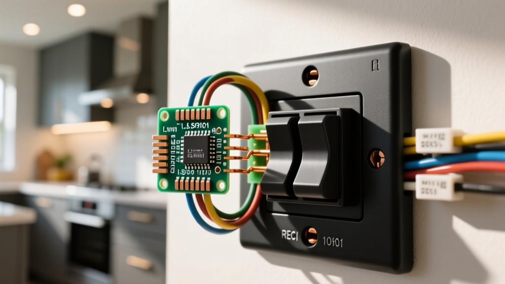
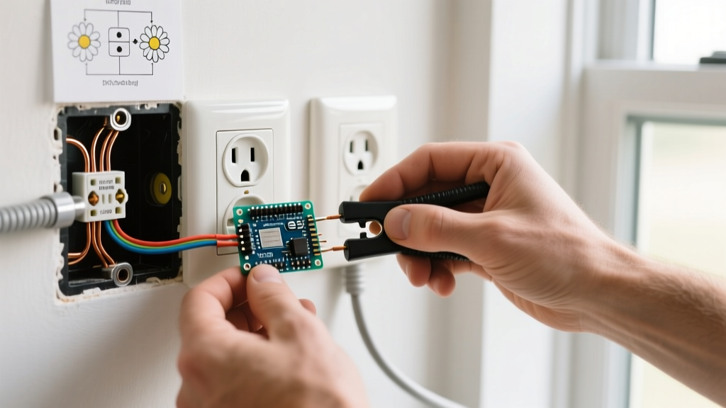
Upgrading to smart lighting (e.g., Lutron Caseta Diva DVRF-6L or Leviton Decora Smart DW15S) fundamentally changes electric switch wiring requirements. Smart switches contain internal radios (Wi-Fi, Zigbee, or proprietary RF) and microprocessors that require continuous standby power.
Neutral-Required vs. Neutral-Free Topologies
- Neutral-Required Switches: These connect to Line, Load, Ground, and the Neutral wire. The neutral completes the 120V circuit for the switch's internal power supply. This is the preferred, most reliable method for high-wattage or non-dimmable LED loads.
- Neutral-Free Switches (e.g., Lutron PD-5S-DV): These wire in series with the load, leaking a tiny trickle of current through the bulb to power the internal electronics. While they solve the problem of older homes lacking neutral wires in the switch box, they often require a bypass capacitor (like the Lutron LUT-MLC) installed at the light fixture to prevent LED flickering or ghosting when the switch is off.
Troubleshooting Electric Switch Wiring Faults
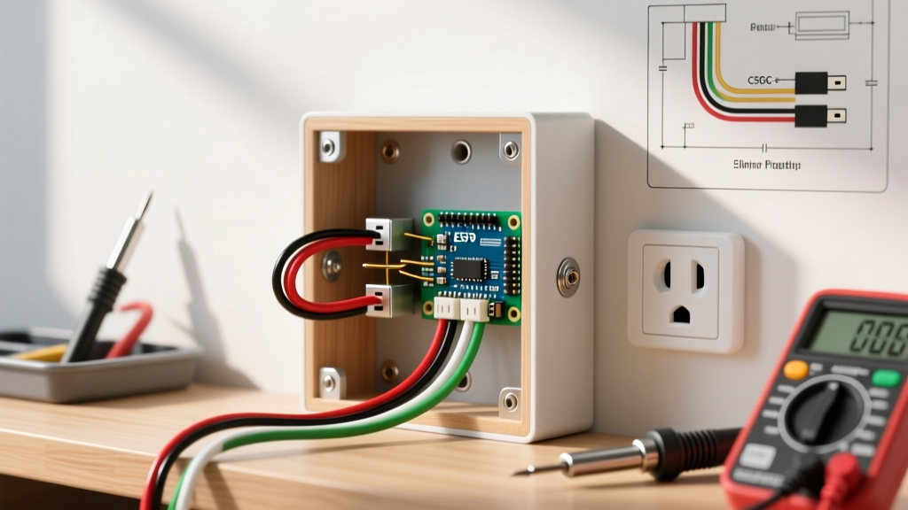
When a newly wired circuit fails to operate, or an existing switch begins to arc or buzz, systematic diagnostics are required. Use a True-RMS multimeter (such as the Fluke 117) set to AC Voltage (V~) and follow this diagnostic flow:
Step-by-Step Voltage Diagnostics
- Verify Line Voltage: With the switch OFF, place the black probe on the Line terminal and the red probe on the Ground screw. You should read 120V (±5%). If 0V, the fault is upstream at the breaker or a loose splice in a preceding junction box.
- Verify Load Continuity: Turn the switch ON. Measure between the Load terminal and Ground. If you read 120V at the switch but the light remains off, the fault is either a burned-out fixture, a broken hot wire between the switch and the fixture, or an open neutral at the fixture canopy.
- Check for Voltage Drop: If the light glows dimly, measure the voltage at the fixture while the switch is ON. A reading below 114V indicates a high-resistance connection, often caused by back-stabbed push-in terminals. Expert Tip: Always use the side-screw terminals or screw-clamp plates rather than push-in backwire holes, which are notorious for loosening under thermal cycling.
Final Code Compliance and Inspection Readiness
Before closing up drywall or installing cover plates, ensure all box fill calculations comply with NEC Article 314. Each 14 AWG wire counts as 2.0 cubic inches, and each internal clamp or device yoke counts as an additional volume allowance. Using oversized deep boxes (e.g., 22 cubic inch single-gang old-work boxes) is highly recommended for smart switch installations to accommodate the bulky wire nuts and the deeper chassis of Wi-Fi enabled relays. For comprehensive safety standards regarding residential electrical installations and fire prevention, always consult the U.S. Consumer Product Safety Commission (CPSC) electrical safety guidelines.